The Art Series' uniquely shaped heatsink is designed for high-efficiency cooling but improper mounting may compromise its ability to cool. When mounting the amplifier in a confined space (i.e. under), care must be taken to ensure that at least two inches of clearance is provided around the amplifier. If the amplifier is located in an area which has restricted air-flow or is totally enclosed, a fan may be used to improve air circulation.
Power and Ground
Before beginning, disconnect the negative (-) terminal of the battery before working on the positive terminal to prevent a short to ground. Reconnect the negative terminal only after all connections have been made.
The Art Series amplifiers are designed to operate from a car's (+) positive 12 volt, negative ground electrical system. PPI recommends that the power and ground cables be a minimum of 6 gauge for the A1200, 10 gauge for the A300 & A600 and 12 gauge for the A100 & A200. Depending upon the complexity of your system, larger gauge wire may be needed. PPI's Exclusive Wire Connection System will accept up to 6 gauge cable.
The main power cable should run from the amplifier location, through the vehicle to the battery, avoiding sharp comers, creases, and sharp body parts. When passing through any metal wall (i.e. fire wall etc.), a grommet must be used to prevent the wire from chaffing and shorting to ground. For safety reasons, PPI recommends that the power cable be fused at the positive terminal of the battery. If this fuse is not installed, and the power wire shorts to ground (between the battery and the amplifier), a fire can result. The fuse at the battery should be of the same value as the chassis fuse located on the right-hand end panel of the amplifier. Consult your Authorized PPI Dealer for an appropriate in-line fuse holder that meets the needs of your installation. We suggest crimping and soldering all wire connections. Insulate the connection with heat shrink to prevent a short to ground.
The ground wire should be of the same gauge as the power wire. As a rule of 'thumb,'use as short a length of wire as possible. Locate an area near the amplifier that is metal (the floor is ideal) and clean an area about the size of a quarter to bare metal. Drill a pilot hole in the middle of this area. Be Careful! Inspect the area under-
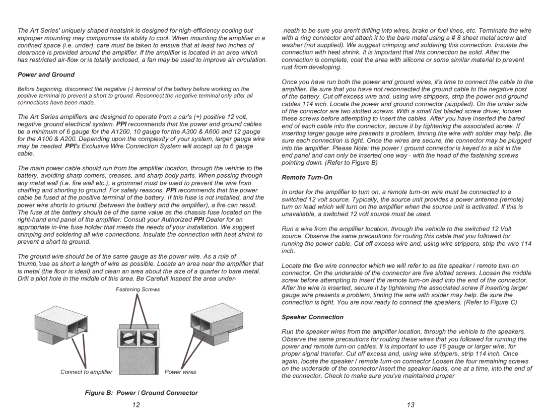
Fastening Screws
Connect to amplifier | Power wires |
Figure B: Power / Ground Connector
neath to be sure you aren't drilling into wires, brake or fuel lines, etc. Terminate the wire with a ring connector and attach it to the bare metal using a # 8 sheet metal screw and washer (not supplied). We suggest crimping and soldering this connection. Insulate the connection with heat shrink. It is important that this connection be solid. After the connection is complete, coat the area with silicone or some similar material to prevent rust from developing.
Once you have run both the power and ground wires, it's time to connect the cable to the amplifier. Be sure that you have not reconnected the ground cable to the negative post of the battery. Cut off excess wire and, using wire strippers, strip the power and ground cables 114 inch. Locate the power and ground connector (supplied). On the under side of the connector are two slotted screws. With a small flat bladed screw driver, loosen these screws before attempting to insert the cables. After you have inserted the bared end of each cable into the connector, secure it by tightening the associated screw. If inserting larger gauge wire presents a problem, tinning the wire with solder may help. Be sure each connection is tight. Once the wires are secure, the connector may be plugged into the amplifier. Please Note: the power / ground connector is keyed to a slot in the end panel and can only be inserted one way - with the head of the fastening screws pointing down. (Refer to Figure B)
Remote Turn-On
In order for the amplifier to turn on, a remote turn-on wire must be connected to a switched 12 volt source. Typically, the source unit provides a power antenna (remote) turn on lead which will turn on the amplifier when the source unit is activated. If this is unavailable, a switched 12 volt source must be used.
Run a wire from the amplifier location, through the vehicle to the switched 12 Volt source. Observe the same precautions for routing this cable that you followed for running the power cable. Cut off excess wire and, using wire strippers, strip the wire 114 inch.
Locate the five wire connector which we will refer to as the speaker / remote turn-on connector. On the underside of the connector are five slotted screws. Loosen the middle screw before attempting to insert the remote turn-on lead into the end of the connector. After the wire is inserted, secure it by tightening the associated screw If inserting larger gauge wire presents a problem, tinning the wire with solder may help. Be sure the connection is tight. You are now ready to connect the speakers. (Refer to Figure C)
Speaker Connection
Run the speaker wires from the amplifier location, through the vehicle to the speakers. Observe the same precautions for routing these wires that you followed for running the power and remote turn-on cables. It is important to use 16 gauge or larger wire, for proper signal transfer. Cut off excess and, using wire strippers, strip 114 inch. Once again, locate the speaker / remote turn-on connector Loosen the four remaining screws on the underside of the connector Insert the speaker leads, one at a time, into the end of the connector. Check to make sure you've maintained proper