I I I . I N S T A L L A T I O N
NOTE: Make sure the hitch bolt is tightened firmly before securing the nut to the hitch assembly to minimize the chance that the lift will tilt during transport.
NOTE: Make sure the hitch tube and lift platform are parallel to the ground before operating the lift system. An angled hitch tube may cause unreliable lift operation and/or damage to the lift system.
5. Route the lift system wiring harness through the vehicle. Refer to “Wiring Harness Installation.”
WARNING! Prevent product damage! Route the wiring harness through the vehicle rather than under the vehicle to avoid coming in contact with sharp edges, extreme temperatures, moving parts, and roadway debris including road salt and other highly corrosive materials. Power shorts may occur if wires come in contact with hot exhaust parts or sharp edges.
WARNING! Never attach the wiring harness to a secondary power source. Do not attempt to use trailer wiring to power the lift system. The wiring harness must be connected directly to the vehicle battery.
NOTE: If your lift is equipped with an onboard battery, refer to “Onboard Battery Installation.”
6. Install the lift platform kit. Refer to the instructions supplied with the kit.
Wiring Harness Installation
The wiring harness is approximately 25 ft. (7.62 meters) long and will accommodate most vehicles.
NOTE: You may wish to perform a practice run before installing the wiring harness. Route a piece of light rope (equivalent to the gage of the wiring harness) along the anticipated path observing contact points, potential rubbing/chafing points, and any sharp edges. Remove sharp edges with a fine grade file, then treat the steel with a rust inhibitor or metal sealant.
Follow these steps to route the Exterior Lift System wiring harness:
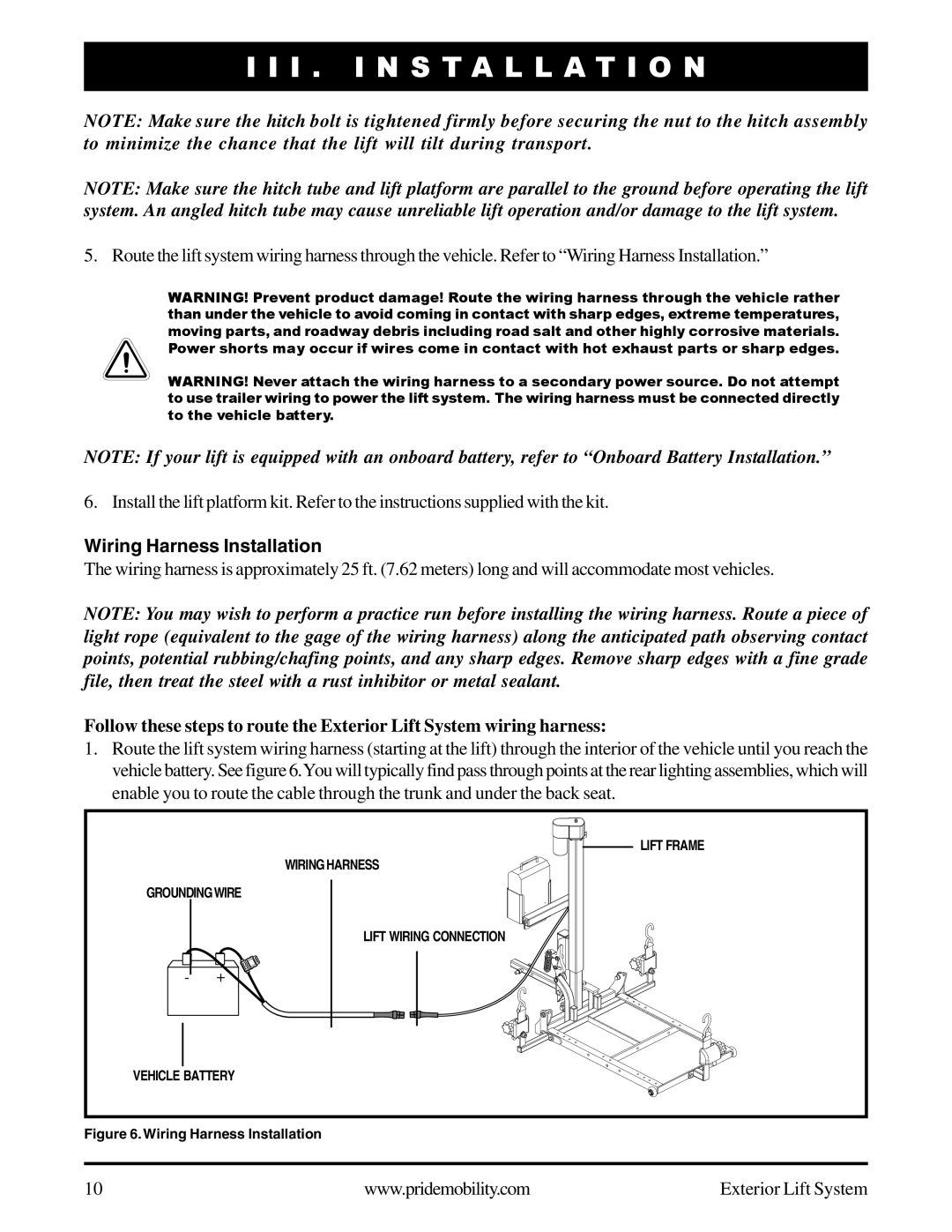
1.Route the lift system wiring harness (starting at the lift) through the interior of the vehicle until you reach the vehicle battery. See figure 6.You will typically find pass through points at the rear lighting assemblies, which will enable you to route the cable through the trunk and under the back seat.
LIFT FRAME
WIRING HARNESS
GROUNDINGWIRE
LIFT WIRING CONNECTION
VEHICLE BATTERY
Figure 6. Wiring Harness Installation
10 | www.pridemobility.com | Exterior Lift System |