ASSEMBLY
Assembly requires two people. Place all parts of the PROFORM¨ 485E in a cleared area and remove the packing materials. Do not dispose of the packing materials until assembly is completed.
Assembly requires a phillips screwdriver ![]()
![]() , two adjustable wrenches
, two adjustable wrenches ![]()
![]() , and a rubber
, and a rubber
mallet![]() .
.
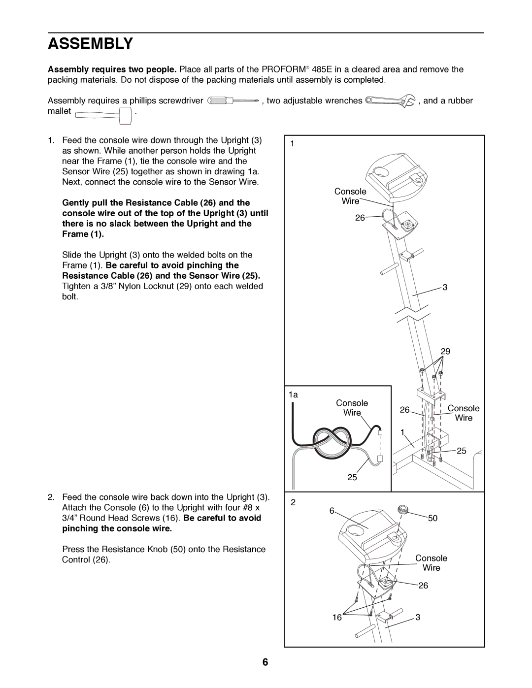
1.Feed the console wire down through the Upright (3) as shown. While another person holds the Upright near the Frame (1), tie the console wire and the Sensor Wire (25) together as shown in drawing 1a. Next, connect the console wire to the Sensor Wire.
Gently pull the Resistance Cable (26) and the console wire out of the top of the Upright (3) until there is no slack between the Upright and the Frame (1).
Slide the Upright (3) onto the welded bolts on the Frame (1). Be careful to avoid pinching the
Resistance Cable (26) and the Sensor Wire (25).
Tighten a 3/8Ó Nylon Locknut (29) onto each welded bolt.
2.Feed the console wire back down into the Upright (3). Attach the Console (6) to the Upright with four #8 x 3/4Ó Round Head Screws (16). Be careful to avoid pinching the console wire.
Press the Resistance Knob (50) onto the Resistance Control (26).
1 |
|
| |
Console |
|
| |
Wire |
|
| |
26 |
|
| |
|
| 3 | |
|
| 29 | |
1a |
|
| |
Console | 26 | Console | |
Wire | |||
| Wire | ||
|
| ||
| 1 |
| |
|
| 25 | |
25 |
|
| |
2 |
|
| |
6 |
| 50 | |
|
| ||
|
| Console | |
|
| Wire | |
|
| 26 | |
16 |
| 3 |
6