ASSEMBLY
Assembly requires two people. Set the treadmill in a cleared area and remove all packing materials. Do not dispose of the packing materials until assembly is completed. Assembly requires your own Phillips screw-
driver 
 , wire cutters
  , and a rubber mallet
  .
.
Note: The underside of the treadmill walking belt is coated with
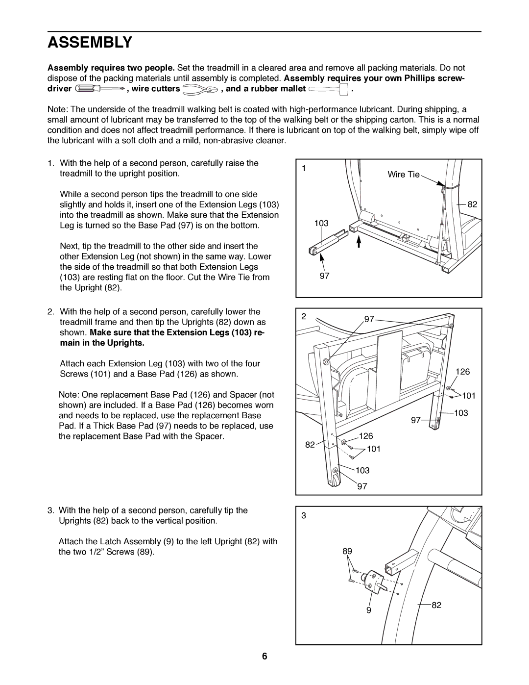
1.With the help of a second person, carefully raise the treadmill to the upright position.
While a second person tips the treadmill to one side slightly and holds it, insert one of the Extension Legs (103) into the treadmill as shown. Make sure that the Extension Leg is turned so the Base Pad (97) is on the bottom.
Next, tip the treadmill to the other side and insert the other Extension Leg (not shown) in the same way. Lower the side of the treadmill so that both Extension Legs (103) are resting flat on the floor. Cut the Wire Tie from the Upright (82).
2.With the help of a second person, carefully lower the treadmill frame and then tip the Uprights (82) down as shown. Make sure that the Extension Legs (103) re- main in the Uprights.
Attach each Extension Leg (103) with two of the four Screws (101) and a Base Pad (126) as shown.
Note: One replacement Base Pad (126) and Spacer (not shown) are included. If a Base Pad (126) becomes worn and needs to be replaced, use the replacement Base Pad. If a Thick Base Pad (97) needs to be replaced, use the replacement Base Pad with the Spacer.
3.With the help of a second person, carefully tip the Uprights (82) back to the vertical position.
Attach the Latch Assembly (9) to the left Upright (82) with the two 1/2Ó Screws (89).
1 |
| Wire Tie |
|
| |
|
| 82 |
103 |
|
|
97 |
|
|
2 | 97 |
|
|
| |
|
| 126 |
|
| 101 |
|
| 103 |
|
| 97 |
82 | 126 |
|
101 |
| |
|
| |
| 103 |
|
| 97 |
|
3 |
|
|
| 89 |
|
| 9 | 82 |
|
|
6