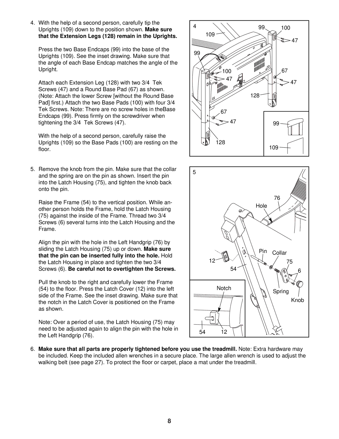
4. With the help of a second person, carefully tip the | 4 | 99 | 100 |
Uprights (109) down to the position shown. Make sure | |||
that the Extension Legs (128) remain in the Uprights. |
| 109 | 47 |
|
|
| |
Press the two Base Endcaps (99) into the base of the | 99 |
|
|
Uprights (109). See the inset drawing. Make sure that |
|
| |
|
|
| |
the angle of each Base Endcap matches the angle of the |
|
|
|
Upright. |
| 100 | 67 |
Attach each Extension Leg (128) with two 3/4” Tek |
| 47 | 47 |
|
| ||
Screws (47) and a Round Base Pad (67) as shown. |
| 128 |
|
(Note: Attach the lower Screw [without the Round Base |
|
| |
Pad] first.) Attach the two Base Pads (100) with four 3/4” |
|
|
|
Tek Screws. Note: There are no screw holes in theBase |
| 67 |
|
Endcaps (99). Press firmly on the screwdriver when |
|
| |
| 47 |
| |
tightening the 3/4” Tek Screws (47). |
| 99 | |
With the help of a second person, carefully raise the |
|
|
|
Uprights (109) so the Base Pads (100) are resting on the |
| 128 | 109 |
floor. |
|
| |
5. Remove the knob from the pin. Make sure that the collar | 5 |
|
|
and the spring are on the pin as shown. Insert the pin |
|
| |
|
|
| |
into the Latch Housing (75), and tighten the knob back |
|
|
|
onto the pin. |
|
|
|
Raise the Frame (54) to the vertical position. While an- |
|
| 76 |
| Hole |
| |
other person holds the Frame, hold the Latch Housing |
|
| |
|
|
| |
(75) against the inside of the Frame. Thread two 3/4” |
|
|
|
Screws (6) several turns into the Latch Housing and the |
|
|
|
Frame. |
|
|
|
Align the pin with the hole in the Left Handgrip (76) by |
|
|
|
sliding the Latch Housing (75) up or down. Make sure |
| Pin | Collar |
that the pin can be inserted fully into the hole. Hold |
| ||
| 12 | 75 | |
the Latch Housing in place and tighten the two 3/4” |
| ||
Screws (6). Be careful not to overtighten the Screws. |
| 54 | 6 |
|
|
| |
Pull the knob to the right and carefully lower the Frame |
| Notch |
|
(54) to the floor. Press the Latch Cover (12) into the left |
| Spring | |
side of the Frame. See the inset drawing. Make sure that |
|
| |
|
| Knob | |
the notch in the Latch Cover is positioned on the Frame |
|
| |
|
|
| |
as shown. |
|
|
|
Note: Over a period of use, the Latch Housing (75) may |
|
|
|
need to be adjusted again to align the pin with the hole in | 54 | 12 |
|
the Left Handgrip (76). |
| ||
|
|
|
6.Make sure that all parts are properly tightened before you use the treadmill. Note: Extra hardware may be included. Keep the included allen wrenches in a secure place. The large allen wrench is used to adjust the walking belt (see page 27). To protect the floor or carpet, place a mat under the treadmill.
8