MAINTENANCE AND STORAGE
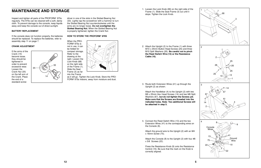
1.Loosen the Lock Knob (68) on the right side of the Frame (1). Slide the Seat Frame (3) out until it stops. Tighten the Lock Knob.
1 | 1 |
| |
| 68 |
Inspect and tighten all parts of the PROFORM¨ 975s regularly. The 975s can be cleaned with a soft, damp cloth. To prevent damage to the console, keep liquids away and keep the console out of direct sunlight.
BATTERY REPLACEMENT
If the console does not function properly, the batteries should be replaced. To replace the batteries, refer to assembly step 11 on page 7.
CRANK ADJUSTMENT
driver in one of the slots in the Slotted Bearing Nut (33). Lightly tap the screwdriver with a hammer to turn the Slotted Bearing Nut counterclockwise until the arms are no longer loose. Do not overtighten the Slotted Bearing Nut. When the Slotted Bearing Nut is properly tightened, tighten the Crank Nut.
HOW TO STORE THE PROFORM¨ 975S
When the PRO- |
| |
FORM¨ 975s is | 1 | |
not in use, it can | ||
68 | ||
be folded for |
|
2. Attach the Upright (2) to the Frame (1) with three |
M10 x 25mm Button Head Screws (25) and three |
3 |
2 |
If the arms of the Crank (14) become loose, they should be tightened in order to prevent excessive wear. Loosen the Crank Nut (35) on the left arm of the Crank. Place the end of a standard screw-
33 |
35 |
14 |
compact storage. |
|
Refer to the |
|
drawing at the |
|
right. Loosen the |
|
Lock Knob (68) | 3 |
on the right side |
|
of the Frame (1). |
|
Slide the Seat |
|
Frame (3) as far |
|
into the Frame |
|
as it will go. Tighten the Lock Knob. Store the PRO- FORM¨ 975s indoors, away from moisture and dust.
M10 Split Washers (26). Be careful not to pinch |
the Reed Switch Wire (13) or the Resistance |
Cable (10). |
3.Route both Extension Wires (41) up through the Upright (2) as shown.
Attach the Handlebar (4) to the Upright (2) with two M6 x 25mm Hex Head Screws (14) and two M6 Split Washers (67), but do not tighten the Screws yet.
Make sure that the Screws are threaded into the indicated holes. Note: Two additional Screws will be attached in step 5.
4.Connect the Reed Switch Wire (13) and the two Extension Wires (41) to the corresponding wires on the Console (8).
Attach the ground wire to the Upright (2) with an M4 x 16mm Screw (75).
Attach the Console (8) to the Upright (2) with four #8 x 5/8Ó Screws (22).
Press the Resistance Knob (9) onto the Resistance Control (10). Be sure that the mark on the Knob is correctly aligned.
| 2 |
|
|
|
|
| 25 |
| 26 |
| 26 |
|
|
| 25 |
| 25 | 10 | 13 |
|
| ||
|
|
| |
|
|
| 1 |
3 |
|
|
|
|
|
| 14 |
| 67 |
| 67 |
|
|
| |
|
|
| 41 |
| 14 |
| 4 |
| 2 |
|
|
4 | 8 |
|
|
|
| 9 | |
|
|
| |
| Console |
|
|
| Wires |
|
|
| 13 |
| 41 |
|
| Ground | |
| 75 |
| |
|
| Wire | |
| 22 |
| 10 |
|
| 2 |
|
|
|
| 22 |
12
5