ASSEMBLY
Assembly requires two people. Set the treadmill in a cleared area and remove all packing materials. Do not dispose of the packing materials until assembly is completed. Assembly requires the included allen wrench
and your own phillips screwdriver 
 and rubber mallet
  .
.
Note: The underside of the treadmill walking belt is coated with
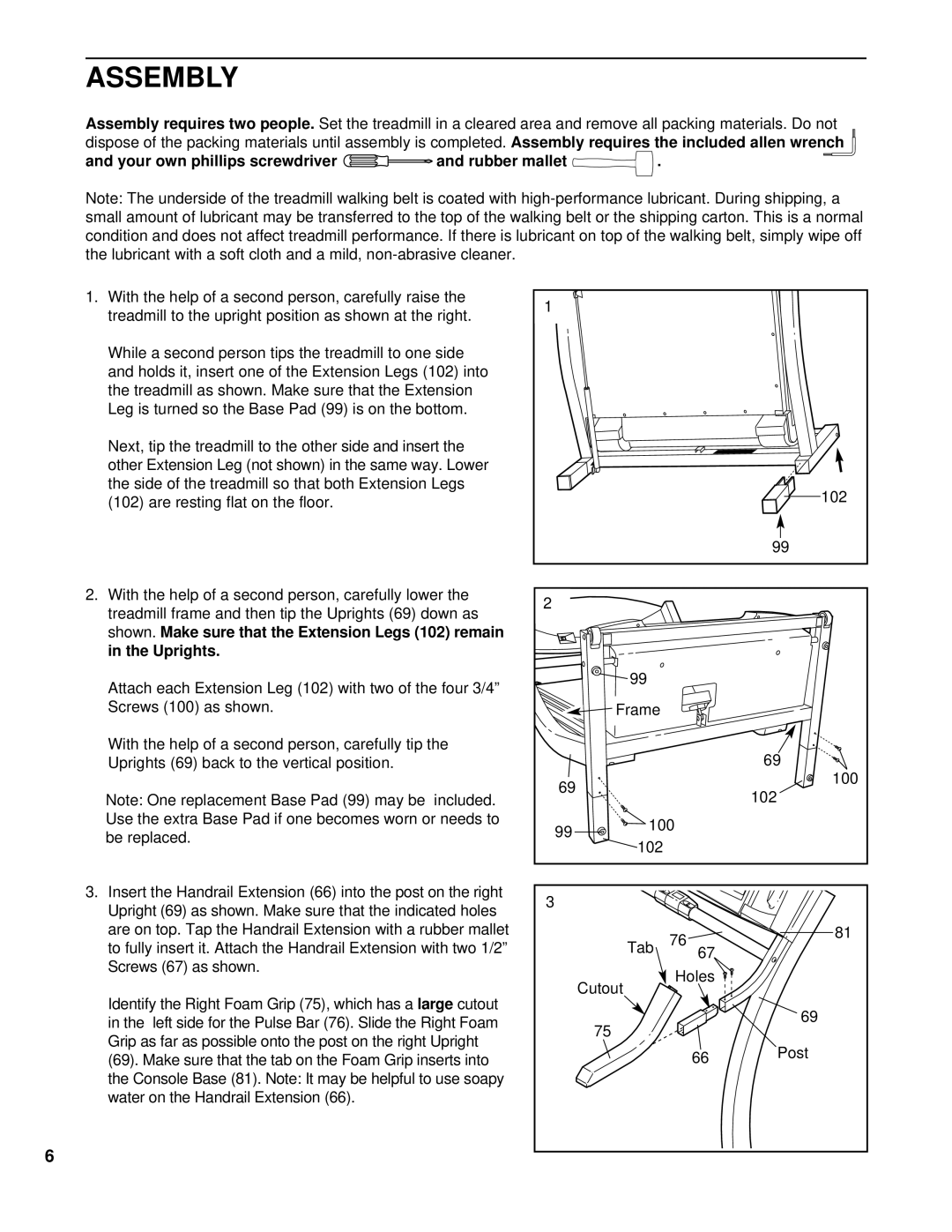
1. With the help of a second person, carefully raise the | 1 |
|
|
|
treadmill to the upright position as shown at the right. |
|
|
| |
|
|
|
| |
While a second person tips the treadmill to one side |
|
|
|
|
and holds it, insert one of the Extension Legs (102) into |
|
|
|
|
the treadmill as shown. Make sure that the Extension |
|
|
|
|
Leg is turned so the Base Pad (99) is on the bottom. |
|
|
|
|
Next, tip the treadmill to the other side and insert the |
|
|
|
|
other Extension Leg (not shown) in the same way. Lower |
|
|
|
|
the side of the treadmill so that both Extension Legs |
|
|
| 102 |
(102) are resting flat on the floor. |
|
|
| |
|
|
|
| |
|
|
|
| 99 |
2. With the help of a second person, carefully lower the | 2 |
|
|
|
treadmill frame and then tip the Uprights (69) down as |
|
|
| |
|
|
|
| |
shown. Make sure that the Extension Legs (102) remain |
|
|
|
|
in the Uprights. |
|
|
|
|
Attach each Extension Leg (102) with two of the four 3/4” |
| 99 |
|
|
|
|
|
| |
Screws (100) as shown. |
| Frame |
|
|
With the help of a second person, carefully tip the |
|
|
| 69 |
Uprights (69) back to the vertical position. |
|
|
| |
| 69 |
|
| 100 |
Note: One replacement Base Pad (99) may be included. |
|
| 102 | |
|
|
| ||
Use the extra Base Pad if one becomes worn or needs to | 99 | 100 |
| |
be replaced. |
| |||
102 |
|
| ||
|
|
| ||
|
|
|
| |
3. Insert the Handrail Extension (66) into the post on the right | 3 |
|
|
|
Upright (69) as shown. Make sure that the indicated holes |
|
|
| |
|
|
|
| |
are on top. Tap the Handrail Extension with a rubber mallet |
| Tab | 76 | 81 |
to fully insert it. Attach the Handrail Extension with two 1/2” |
|
| ||
Screws (67) as shown. |
|
| 67 |
|
|
| Holes |
| |
|
| Cutout |
| |
Identify the Right Foam Grip (75), which has a large cutout |
|
|
| |
|
|
| 69 | |
in the left side for the Pulse Bar (76). Slide the Right Foam |
| 75 |
| |
|
|
| ||
Grip as far as possible onto the post on the right Upright |
|
|
| |
|
| 66 | Post | |
(69). Make sure that the tab on the Foam Grip inserts into |
|
| ||
|
|
| ||
the Console Base (81). Note: It may be helpful to use soapy |
|
|
|
|
water on the Handrail Extension (66). |
|
|
|
|
6