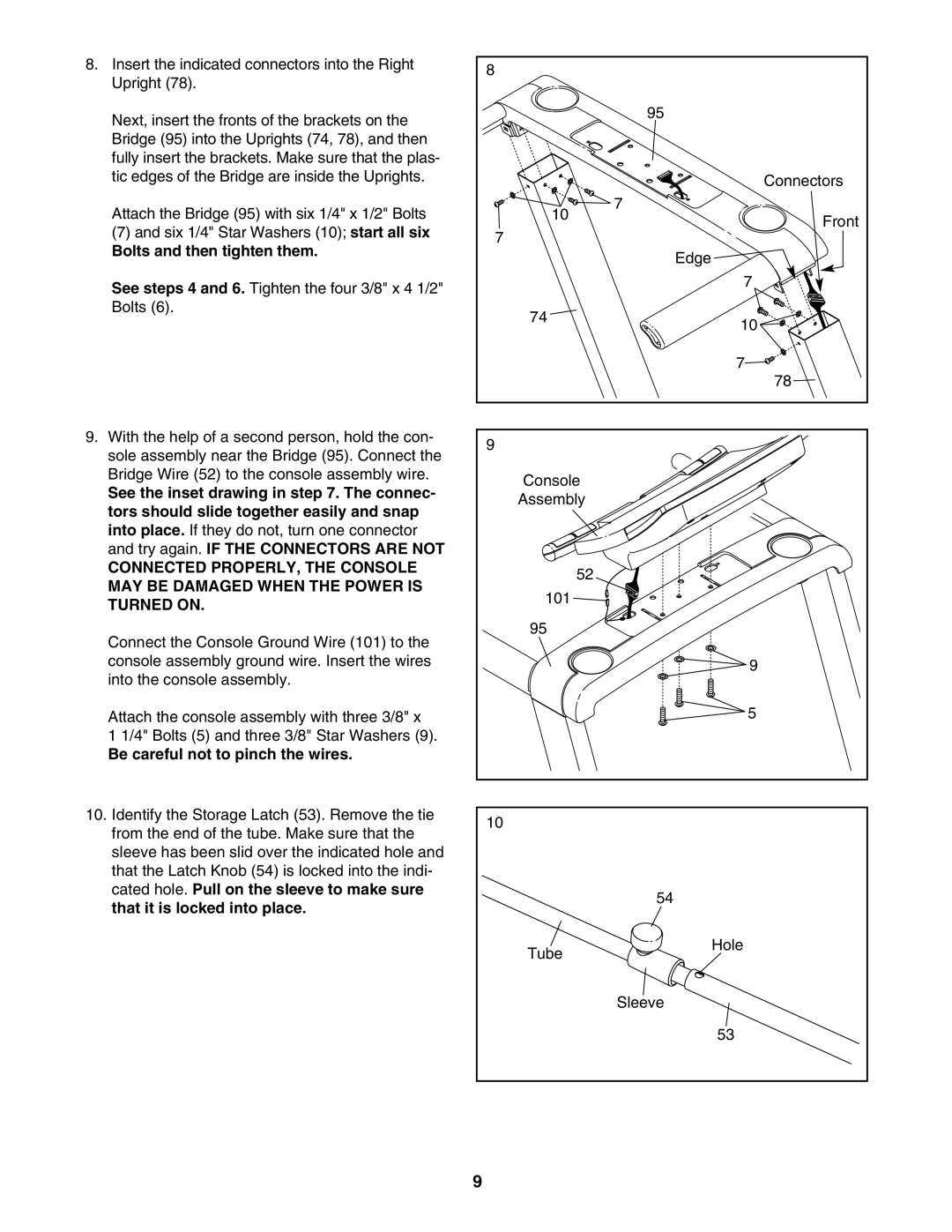
8. Insert the indicated connectors into the Right | 8 |
| |
Upright (78). |
| ||
|
| ||
Next, insert the fronts of the brackets on the |
| 95 | |
|
| ||
Bridge (95) into the Uprights (74, 78), and then |
|
| |
fully insert the brackets. Make sure that the plas- |
|
| |
tic edges of the Bridge are inside the Uprights. |
| Connectors | |
Attach the Bridge (95) with six 1/4" x 1/2" Bolts | 10 | 7 | |
Front | |||
(7) and six 1/4" Star Washers (10); start all six | 7 | ||
| |||
Bolts and then tighten them. |
| ||
| Edge | ||
|
| ||
See steps 4 and 6. Tighten the four 3/8" x 4 1/2" |
| 7 | |
|
| ||
Bolts (6). | 74 |
| |
| 10 | ||
|
| ||
|
| 7 | |
|
| 78 | |
9. With the help of a second person, hold the con- | 9 |
| |
sole assembly near the Bridge (95). Connect the |
| ||
|
| ||
Bridge Wire (52) to the console assembly wire. | Console |
| |
See the inset drawing in step 7. The connec- |
| ||
Assembly |
| ||
tors should slide together easily and snap |
| ||
|
| ||
into place. If they do not, turn one connector |
|
| |
and try again. IF THE CONNECTORS ARE NOT |
|
| |
CONNECTED PROPERLY, THE CONSOLE | 52 |
| |
MAY BE DAMAGED WHEN THE POWER IS |
| ||
101 |
| ||
TURNED ON. |
| ||
|
| ||
Connect the Console Ground Wire (101) to the | 95 |
| |
|
| ||
console assembly ground wire. Insert the wires |
| 9 | |
into the console assembly. |
|
| |
Attach the console assembly with three 3/8" x |
| 5 | |
1 1/4" Bolts (5) and three 3/8" Star Washers (9). |
|
| |
Be careful not to pinch the wires. |
|
| |
10. Identify the Storage Latch (53). Remove the tie | 10 |
| |
from the end of the tube. Make sure that the |
| ||
|
| ||
sleeve has been slid over the indicated hole and |
|
| |
that the Latch Knob (54) is locked into the indi- |
|
| |
cated hole. Pull on the sleeve to make sure |
| 54 | |
that it is locked into place. |
| ||
|
| ||
| Tube | Hole | |
|
| ||
|
| Sleeve | |
|
| 53 | |
| 9 |
|