START-UP PROCEDURES AND OPERATION

1.Some PVI atmospheric gas-fired water heaters are designed to operate with a flue damper that is shipped with the water heater for installation in the field. If your water heater was shipped with a flue damper, it must be attached to the flue collector and interconnected to the ignition control module before proceeding with start-up.

Flue Damper Installation

a.Set the flue damper over the flue collector opening and align the damper drive housing to the front of the heater.

b.Secure the flue damper to the flue collector at three locations using the fasteners provided.

c.Remove the damper drive housing cover, feed the damper interconnect cable through the access hole and attach the female connector to the four-pin receptacle. Secure the access hole cover, check to make sure the test switch is in the "NORMAL" position, and reattach the damper driver housing cover.

CAUTION: BE SURE THERE IS NO FOREIGN MATTER IN THE DAMPER HOUSING BEFORE ATTACHING THE DRAFT DIVERTER.

Draft Diverter Installation

The draft diverter (provided) is designed to mount on top of the flue damper. Set the draft diverter on top of the flue damper and secure in three locations using the fasteners provided.

Venting

Type B galvanized vent pipe, of the same diameter as the draft diverter outlet, must be installed to route combustion products either to existing overhead breeching or to an appropriate outside location.

1.The control manufacturer's installation and service manual and start-up procedures for the control system on your water heater are shipped with the unit. Study the information carefully and follow the manufacturer's recommendations.

2.Fill the water heater tank with water. Open the relief valve or a nearby hot water faucet to allow air in the tank to escape. Be sure all connections into the tank are tight as leaks at tank fittings will damage the insulation.

3.Remove the control box cover to access the control thermostats and other electrical devices needed to operate the water heater. The thermostats are labeled as to their function. The temperature limiting device is set at 200°F. The thermostats are factory set at 130°F. (the upper operating thermostat) and 120°F (the operating thermostat). Adjustment may be made by turning the thermostat dial to the desired temperature.

CAUTION: BE SURE TO REATTACH THE CONTROL BOX COVER TO HELP PREVENT UNAUTHORIZED ACCESS TO CONTROLS.

CAUTION: DO NOT OVERTIGHTEN COMPRESSION FITTINGS ON THERMOSTAT BULBS AS CALIBRATION WILL BE CHANGED.

CAUTION: TEMPERATURES HIGHER THAN 125°F INCREASE THE RISK OF SCALD INJURY!

Gas Train Safety Inspection

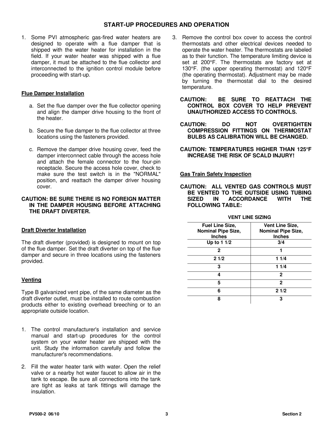
CAUTION: ALL VENTED GAS CONTROLS MUST BE VENTED TO THE OUTSIDE USING TUBING SIZED IN ACCORDANCE WITH THE FOLLOWING TABLE:

VENT LINE SIZING


Fuel Line Size,

Vent Line Size,

Nominal Pipe Size,

Nominal Pipe Size,

Inches

Inches

Up to 1 1/2

3/4


2


1


2 1/2

1

1/4


3

1 1/4


4


2


5


2


6

2 1/2


8


3


PV500-2 06/10

3

Section 2

Page 3
Image 3
PVI Industries PV500-2 START-UP Procedures and Operation, Flue Damper Installation, Draft Diverter Installation, Venting

PV500-2 specifications

The PVI Industries PV500-2 is a cutting-edge photovoltaic (PV) inverter designed to maximize the efficiency and reliability of solar energy systems. With a focus on both residential and commercial applications, the PV500-2 combines innovative technologies and features that cater to the evolving needs of the solar energy market.

One of the standout features of the PV500-2 is its powerful output capacity. With a maximum output of 500 kW, this inverter is capable of handling large-scale solar installations. This makes it an excellent choice for utility-scale solar farms, commercial rooftops, and other applications where high energy demand needs to be met efficiently. The inverter's superior performance is complemented by its high efficiency rating, often exceeding 98%. This translates to more energy harvested from solar panels, leading to improved return on investment for users.

The PV500-2 also integrates advanced monitoring capabilities. Equipped with a smart inverter technology, it supports real-time performance tracking, helping users to monitor energy production and optimize system performance remotely. This feature is particularly beneficial for system operators and owners, as it allows for quick identification of issues and facilitates proactive maintenance.

In terms of safety and durability, the PV500-2 is designed to withstand harsh environmental conditions. Its robust construction guarantees longevity, while built-in safety features such as overvoltage protection, overcurrent protection, and ground fault monitoring provide peace of mind against potential hazards.

Another notable characteristic of the PV500-2 is its compatibility with various solar technologies. It can efficiently work with both string and central inverters, making it versatile for different installations. This flexibility ensures that users can easily integrate the inverter into existing systems or new setups without significant adjustments.

Furthermore, the inverter's compact design and lightweight structure simplify installation, even in space-constrained settings. This is crucial for reducing labor costs and enhancing installation efficiency.

In conclusion, the PVI Industries PV500-2 stands out in the competitive landscape of solar inverters due to its high output capacity, advanced monitoring features, and robust safety measures. Its versatility and ease of installation make it an excellent choice for a wide range of solar applications, catering to the growing demands of renewable energy users. As the transition to solar energy continues, the PV500-2 provides a reliable solution for those looking to harness the power of the sun efficiently and effectively.