PT610 specifications
PYLE Audio PT610 is a versatile and powerful audio amplifier designed for both home and professional use. This robust unit combines impressive sound quality with user-friendly features, making it a top choice for audiophiles and casual listeners alike.One of the standout characteristics of the PT610 is its ability to deliver a powerful peak output of 1000 watts. This ample power ensures that your audio experience is both dynamic and immersive, whether you are listening to music, watching movies, or hosting a party. The amplifier is capable of driving multiple speakers, making it suitable for larger spaces and gatherings.
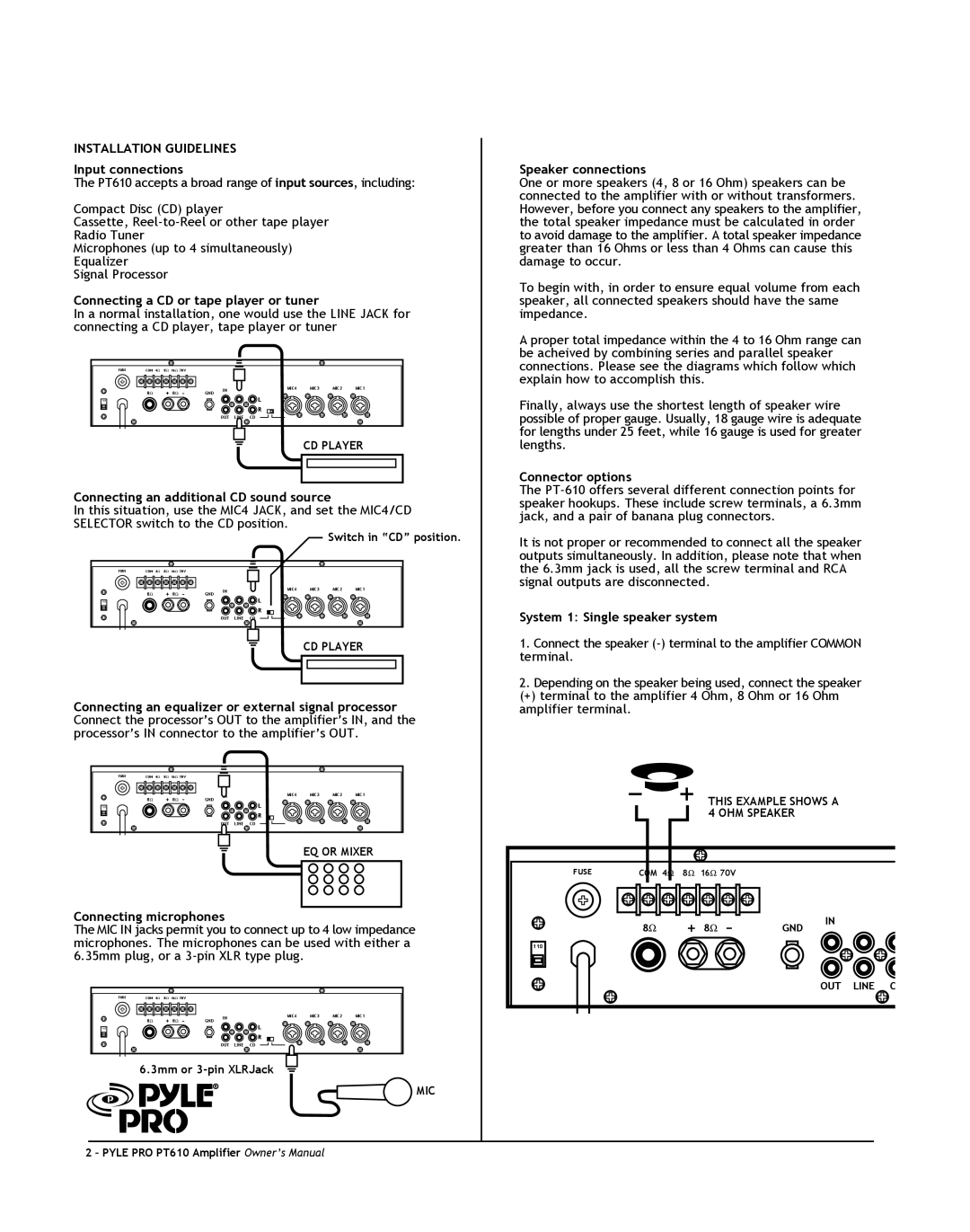
The PT610 also boasts a range of connectivity options, including Bluetooth compatibility. This feature allows users to stream audio wirelessly from their smartphones, tablets, or computers, providing a seamless experience without the hassle of tangled wires. Additionally, it has RCA inputs, enabling you to connect external devices such as CD players, DVD players, and other audio sources.
Another significant feature of the PYLE Audio PT610 is its built-in equalizer. This allows users to adjust the sound profile to their liking, enhancing the listening experience across various genres of music. The amplifier offers adjustment controls for bass, treble, and balance, allowing for personalized sound tuning.
Moreover, this audio amplifier is designed with durability in mind. The chassis is constructed from high-quality materials that not only provide robustness but also aid in heat dissipation, ensuring optimal performance and longevity. Its sleek and modern design means that it can easily blend into any home theater setup or professional environment.
The PT610 also features short circuit protection, which safeguards both the amplifier and connected equipment against electrical issues. This reliability is essential for users who demand consistent performance, particularly in professional settings where equipment must function flawlessly.
In summary, the PYLE Audio PT610 is a feature-packed audio amplifier designed for versatility and performance. With its powerful output, wireless connectivity, built-in equalizer, and durable construction, it is an ideal choice for anyone seeking to enhance their audio experience, whether at home or in a professional environment.

