Introduction
Thank you and congratulations on your purchase of the AcousticDesign
The
These loudspeakers make an excellent choice for a wide variety of SR applications.
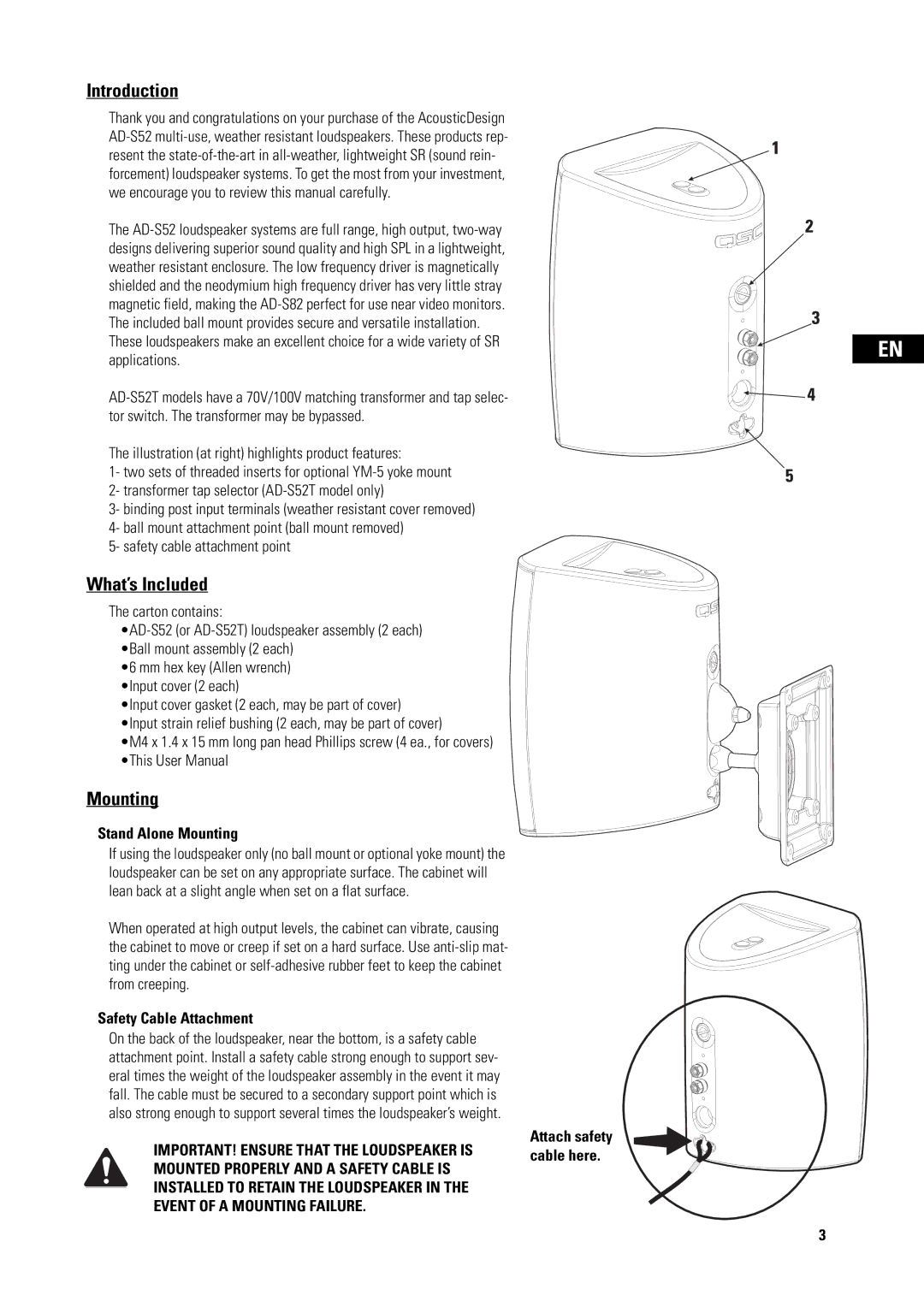
The illustration (at right) highlights product features:
1- two sets of threaded inserts for optional
3- binding post input terminals (weather resistant cover removed) 4- ball mount attachment point (ball mount removed)
5- safety cable attachment point
What’s Included
The carton contains:
•6 mm hex key (Allen wrench) •Input cover (2 each)
•Input cover gasket (2 each, may be part of cover) •Input strain relief bushing (2 each, may be part of cover)
•M4 x 1.4 x 15 mm long pan head Phillips screw (4 ea., for covers) •This User Manual
Mounting
Stand Alone Mounting
If using the loudspeaker only (no ball mount or optional yoke mount) the loudspeaker can be set on any appropriate surface. The cabinet will lean back at a slight angle when set on a flat surface.
When operated at high output levels, the cabinet can vibrate, causing the cabinet to move or creep if set on a hard surface. Use
Safety Cable Attachment
On the back of the loudspeaker, near the bottom, is a safety cable attachment point. Install a safety cable strong enough to support sev- eral times the weight of the loudspeaker assembly in the event it may fall. The cable must be secured to a secondary support point which is also strong enough to support several times the loudspeaker’s weight.
IMPORTANT! ENSURE THAT THE LOUDSPEAKER IS MOUNTED PROPERLY AND A SAFETY CABLE IS INSTALLED TO RETAIN THE LOUDSPEAKER IN THE EVENT OF A MOUNTING FAILURE.
Attach safety cable here.
EN
3
