Instructions for the DDI-3 DataPort Accessory Card
I. INTRODUCTION
The
QSC ISA, CX, DCA, SRA, PowerLight, and PowerLight 2 Series amplifiers feature a DataPort for every two audio channels. Therefore, one- and
VMN1 | STBY | |
CGND | ||
| ||
IMN1 | CH2+ | |
| CH2- | |
IMN2 | AGND | |
| ||
VMN2 | CH1+ | |
CH1- | ||
| ||
| AGND |
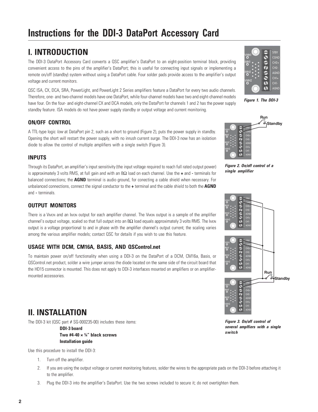
Figure 1. The DDI-3
Run
ON/OFF CONTROL
A
INPUTS
Through its DataPort, an amplifier’s input sensitivity (the input voltage required to reach full rated output power) is approximately 3 volts RMS, at full gain and with an 8Ω load on each channel. Use the + and - terminals for balanced connections; the AGND terminal is audio ground, for conecting a cable shield when necessary. For unbalanced connections, connect the signal conductor to the + terminal and the cable shield to both the AGND and - terminals.
![]() Standby
Standby
VMN1 | STBY | |
CGND | ||
| ||
IMN1 | CH2+ | |
| CH2- | |
IMN2 | AGND | |
|
CH1+
VMN2
CH1-
AGND
Figure 2. On/off control of a single amplifier
OUTPUT MONITORS
There is a VMON and an IMON output for each amplifier channel. The VMON output is a sample of the amplifier channel’s output voltage, scaled so that full output into an 8Ω load equals approximately 3 volts RMS. The IMON output is a voltage proportional to and in phase with the amplifier channel’s output current; the scaling varies among the various amplifier models; contact QSC for details if you wish to use this feature.
USAGE WITH DCM, CM16A, BASIS, AND QSControl.net
To maintain power on/off functionality when using a
II. INSTALLATION
VMN1
IMN1 ![]()
IMN2 ![]()
![]()
![]()
VMN2
VMN1
IMN1 ![]()
IMN2 ![]()
![]()
![]()
VMN2
VMN1
IMN1 ![]()
IMN2 ![]()
![]()
![]()
VMN2
STBY CGND CH2+ CH2-
AGND CH1+ CH1-
AGND
STBY CGND CH2+ CH2-
AGND CH1+ CH1-
AGND
STBY CGND CH2+ CH2-
AGND CH1+ CH1-
AGND
Run
![]()
![]() Standby
Standby
The
DDI-3 board
Two #4-40 × ¼” black screws
Installation guide
Use this procedure to install the
1.Turn off the amplifier.
Figure 3. On/off control of several amplfiers with a single switch
2.If you are using the output voltage or current monitoring features, solder the wires to the appropriate pads on the
3.Plug the
2