QSC Audio HPR153F, HPR151W, HPR181W, HPR152F user manual Application Example #2

Models: HPR152F HPR151W HPR181W HPR153F

1 20
Download 20 pages 23.61 Kb
Page 12
Image 12

Application Example #2

This example shows a two-channel (stereo) setup utilizing one subwoofer and two top-boxes.

Audio signals for the Left and Right channels are supplied by the mixer console. This signal source can be just about any variable-output level audio source, such as DJ mixers, profes- sional CD players, or computer-based audio signal sources.

Audio output from the mixer is connected to the subwoofer’s Left (L) and Right (R) channels. The subwoofer’s R and L FULL RANGE LINE OUT connectors are used to connect to its respec- tive top-box. Turn ON each top-box’s 100 Hz LOW-CUT FILTER.

Alternately, the top-boxes could be connected to the sub- woofer’s 100 Hz LOW-CUT OUT and the top-boxes 100 Hz LOW-CUT FILTERs turned off. The only possible issue with this method of connection is unexpected noises (turn-off thumps) if the subwoofer is powered down before the top-boxes. If con- nected as shown, power sequencing is not an issue.

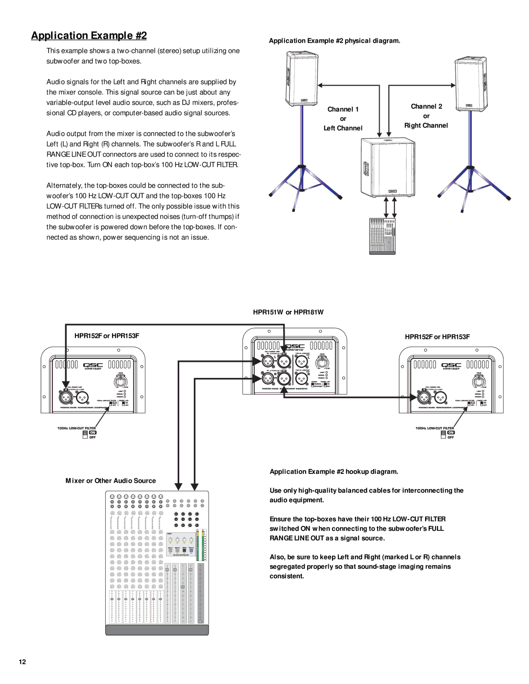
Application Example #2 physical diagram.

Channel 1


Channel 2


or

or


Right Channel

Left Channel


HPR152F or HPR153F

Mixer or Other Audio Source

HPR151W or HPR181W

HPR152F or HPR153F

Application Example #2 hookup diagram.

Use only high-quality balanced cables for interconnecting the audio equipment.

Ensure the top-boxes have their 100 Hz LOW-CUT FILTER switched ON when connecting to the subwoofer’s FULL RANGE LINE OUT as a signal source.

Also, be sure to keep Left and Right (marked L or R) channels segregated properly so that sound-stage imaging remains consistent.

12

Page 12
Image 12
QSC Audio HPR153F, HPR151W, HPR181W, HPR152F user manual Application Example #2