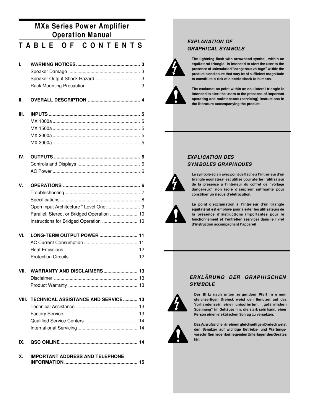
MX2000a, MX 1000a, MX 1500a, MX3000a specifications
The QSC MX series amplifiers, including the MX3000a, MX1500a, MX1000a, and MX2000a, are designed to deliver outstanding audio performance, making them popular choices in both professional audio and live sound environments. Each model combines high-quality components with innovative technologies, ensuring reliability and consistency in sound reproduction.The MX3000a stands out with its powerful output, featuring an impressive peak power of 3000 watts at 4 ohms. It excels in larger venues, providing the headroom needed for demanding audio applications. The amplifier is equipped with advanced thermal management technology and a built-in limiter to ensure safe operation under heavy loads, automatically adjusting output levels to prevent distortion and potential damage to connected speakers.
The MX1500a is an ideal choice for mid-sized applications, delivering 1500 watts at 4 ohms. This model incorporates QSC’s rugged construction, featuring a sturdy chassis and efficient heat dissipation to withstand the rigors of professional use. With its versatile input options, including XLR and quarter-inch connectors, the MX1500a can easily integrate into various audio setups, making it suitable for both live sound reinforcement and permanent installations.
For more compact needs, the MX1000a provides 1000 watts of power at 4 ohms while maintaining exceptional sound clarity. Its lightweight design and efficient power supply make it easy to transport, catering to mobile DJs, small bands, and corporate events. The MX1000a includes a comprehensive set of LED indicators for power, signal, and clipping, allowing users to monitor performance easily.
Lastly, the MX2000a offers a versatile solution with 2000 watts of output at 4 ohms. This amplifier features a high-performance class-H design, ensuring minimal heat generation and improved efficiency. Its dual-channel configuration allows for flexibility in powering two separate speaker systems or bridging the channels for a single high-power output.
All models in the QSC MX series emphasize durability, high-quality sound, and flexible connectivity, making them suitable for a wide range of professional audio applications. With built-in protection circuits, efficient cooling systems, and ease of use, the MX series amplifiers are trusted by audio professionals for their reliability and performance, ensuring that they meet the demands of any event or installation.

