Pro Unidirectional Highball Microphone
OWNER’S MANUAL — Please read before using this equipment.
Your RadioShack Pro Unidirectional Highball Microphone provides the quality performance you need for your PA or recording system. Its uni- directional pickup pattern provides increased tonal sensitivity while re- ducing unwanted sounds and feedback.
Its other features include:
Wire Mesh Windscreen — cuts down on wind noise and breath pops
ON/OFF Switch — for convenient control of the microphone
Choice of 600-ohm or 50-k ohm Impedance — lets you match your
microphone to a wide range of equipment
Microphone Stand Clamp— holds the microphone and lets you place the microphone on a microphone stand (not supplied)
Carrying Pouch — lets you carry your microphone and accessories in a convenient pouch
USING THE MICROPHONE STAND CLAMP
The supplied microphone stand clamp lets you place your microphone on a microphone stand (not supplied). Screw the holder onto the top of a microphone stand. Then slide the microphone into the larger end of the holder until it is secure.
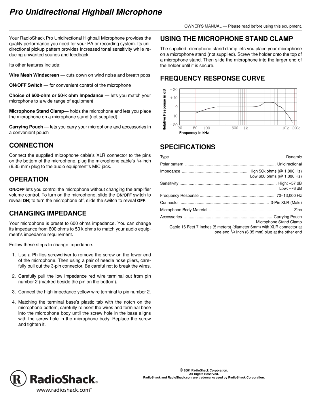
FREQUENCY RESPONSE CURVE
Relative Response in dB
Frequency in kHz
CONNECTION
Connect the supplied microphone cable’s XLR connector to the pins on the bottom of the microphone, plug the microphone cable’s
OPERATION
ON/OFF lets you control the microphone without changing the amplifier volume control. To turn on the microphone, slide the ON/OFF switch to reveal ON; to turn the microphone off, slide the switch to reveal OFF.
CHANGING IMPEDANCE
Your microphone is preset to 600 ohms impedance. You can change its impedance from 600 ohms to 50 k ohms to match your audio equip- ment’s impedance requirement.
Follow these steps to change impedance.
1.Use a Phillips screwdriver to remove the screw on the lower end of the microphone. Then using a pair of needle nose pliers, care- fully pull out the
2.Carefully pull the low impedance red wire terminal out from pin number 2 (marked beside the pin on the bottom).
3.Connect the high impedance yellow wire terminal to pin number 2.
4.Matching the terminal base’s plastic tab with the notch on the microphone bottom, carefully reinsert the wires and terminal base into the microphone body until the screw hole in the base aligns with the screw hole in the microphone body. Replace the screw and tighten it.
SPECIFICATIONS
Type | Dynamic |
Polar pattern | Unidirectional |
Impedance | High 50k ohms (@ 1,000 Hz) |
| Low 600 ohms (@ 1,000 Hz) |
Sensitivity | High: |
| Low: |
Frequency Response | |
Connector | |
Microphone Body Material | Zinc |
Accessories | Carrying Pouch |
| Microphone Stand Clamp |
Cable 16 Feet 7 Inches (5 meters) (diameter 6mm) with XLR connector at one end 1/4 Inch (6.35 mm) plug at the other end
© 2001 RadioShack Corporation.
All Rights Reserved.
RadioShack and RadioShack.com are trademarks used by RadioShack Corporation.