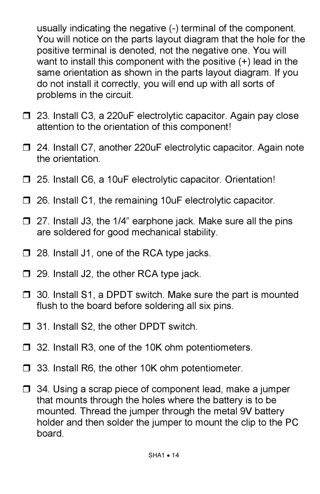
SHA1 specifications
Ramsey Electronics SHA1 is a sophisticated audio amplifier designed for high-quality sound performance in various applications. Known for its compact design and robust features, the SHA1 is suitable for personal audio setups, professional applications, and even educational purposes.One of the standout features of the SHA1 is its ability to deliver powerful sound output while maintaining clarity and fidelity. The amplifier offers a significant wattage that is enough to drive a wide range of speakers effectively. This power ensures that users can enjoy rich sound without distortion, making it a favorite among audiophiles and musicians alike.
The SHA1 incorporates advanced technologies that enhance its performance. For instance, it uses high-quality capacitors and resistors to minimize noise and signal loss. This ensures that the sound produced is pure and true to the original audio source. The use of Class AB amplification technology allows the SHA1 to balance efficiency and sound quality, providing users with an experience that satisfies their audio needs.
Another notable characteristic of the Ramsey Electronics SHA1 is its versatility in input options. It typically supports multiple audio input types, including RCA, 3.5mm auxiliary, and even professional audio inputs, making it compatible with various audio devices, from smartphones to musical instruments. This flexibility ensures that users can easily connect their devices and enjoy seamless audio playback.
User-friendly controls are a significant aspect of the SHA1 design. The amplifier often features straightforward volume controls, tone adjustments, and easily accessible input selections. This simplicity allows users of all skill levels to operate the amplifier without any confusion or technical know-how.
The sleek design of the SHA1 makes it an attractive addition to any audio setup. Its compact size ensures that it can fit into tight spaces, while its stylish aesthetics can complement any decor.
Overall, Ramsey Electronics SHA1 stands out for its combination of power, clarity, versatility, and user-friendly design. Whether for home audio systems, professional use, or educational setups, the SHA1 is a reliable choice for anyone seeking an exceptional listening experience. It embodies Ramsey Electronics’ commitment to quality and performance, making it a well-regarded option in the audio amplifier market.
