Manuals
/
Raypak
/
Household Appliance
/
Boiler
Raypak
0135B, 0030B, 0090B
manual
Models:
0135B
0090B
0030B
1
35
39
39
Download
39 pages
14.16 Kb
32
33
34
35
36
37
38
39
Troubleshooting
Specifications
Install
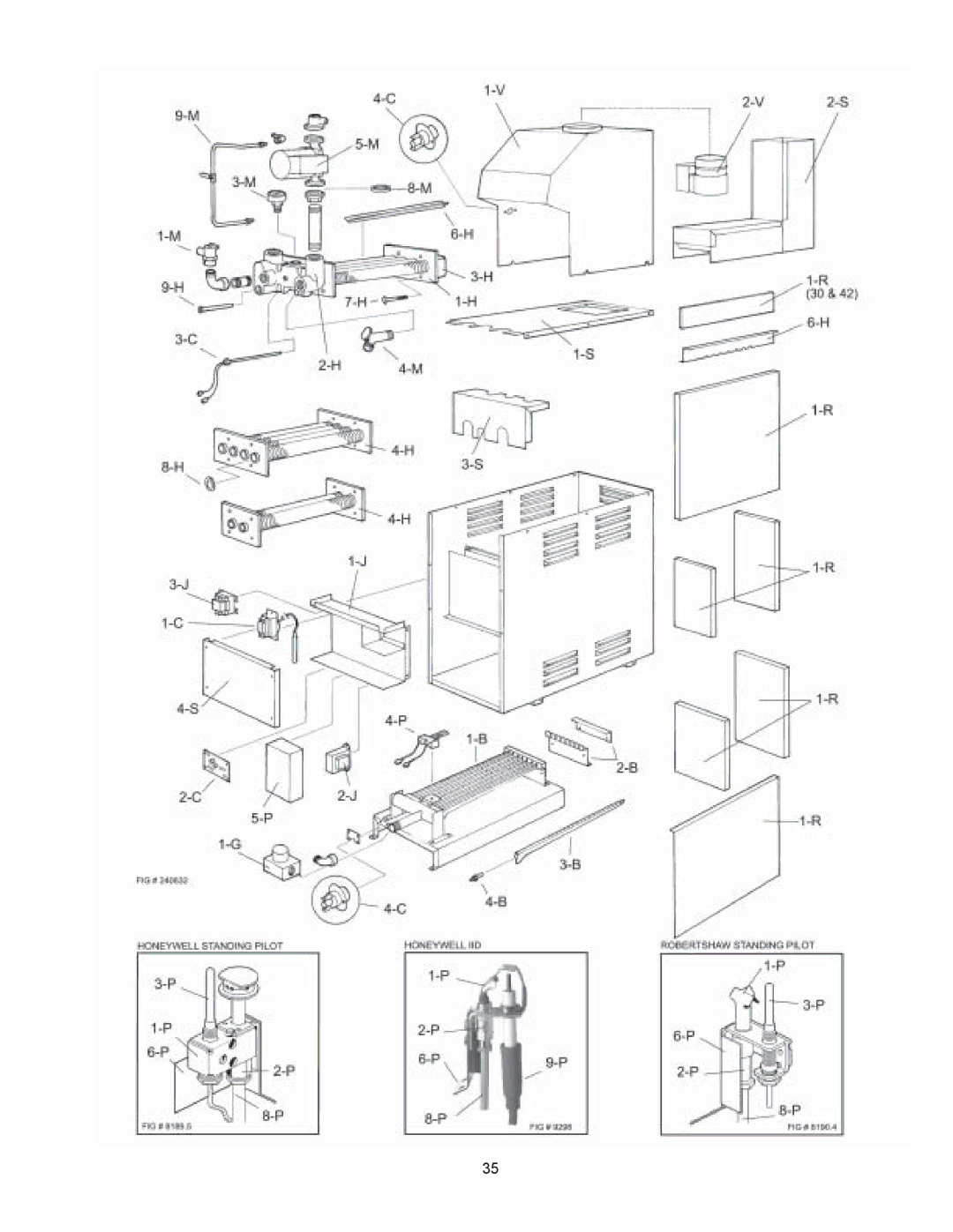
Parts list
D80D General Wiring Diagram
Vent Damper Position Indicator
Electrical Wiring
Warranty
Heat Exchanger RE-ASSEMBLY
Servicing Procedures
Page 35
Image 35
35
Page 34
Page 36
Page 35
Image 35
Page 34
Page 36
Contents
For Your Safety
Installation Operating Instructions
Contents
Receiving Equipment
General Specifications
Specifications and Dimensions
Clearancerequirements
Installation Procedures
Code Requirements
Mounting Base
Fig. #8198.0
Venting Connections
Fig.#
Common Vents
Location
Vent Damper Installation
Mounting
Installing the Vent Damper in Horizontal & Vertical Vent
D80D General Wiring Diagram
Flair Damper
Vent Damper Position Indicator
System Schematic Ladder Diagram
Vent Damper Operation
Connection Diagram
Water Connections & System Piping
GAS Supply Connections
Gaspressure
SINGLE-ZONEPIPING
Piping Diagrams
Zone Heating with Indirect Domestic HOT Water Supply
Multiple Zones with Zone Valves
Fig.#
Electrical Wiring
Wiring Diagram KEY
Page
Page
Wiring Diagram Single-Zone Taco Valve
Wiring Diagram System with 3 Zone Pumps
Fig. #2223.2e
Wiring Diagram Standing Pilot With Low Water Cut-off Device
Sequence of Operation Intermittent Ignition Device IID
Servicing Procedures
General Location of Controls
Control BOX Component Locations Models 135
What to do if YOU Smell GAS
START-UPPROCEDURES
For Automatic Ignition Models
Honeywell Pilot Robertshaw Pilot
To Turn OFF GAS to Boiler
SHUT-DOWNPROCEDURE
For Automatic Ignition Systems
Flame Failure
Inspection Procedures Burners
Inspectionprocedures
Safe SHUT-DOWN Tests Limit Action
Repairprocedures
Raypak Tube Cleaning KIT
Combustion Chamber Removal
Heat Exchanger RE-ASSEMBLY
Important Notice
Troubleshooting Guide
Piping
ADJUSTMENT/REPLACEMENTOF Components
RAYPAK, INC
Replacement Parts List
Page
Page
Page
Limited Parts Warranty
Top
Page
Image
Contents