
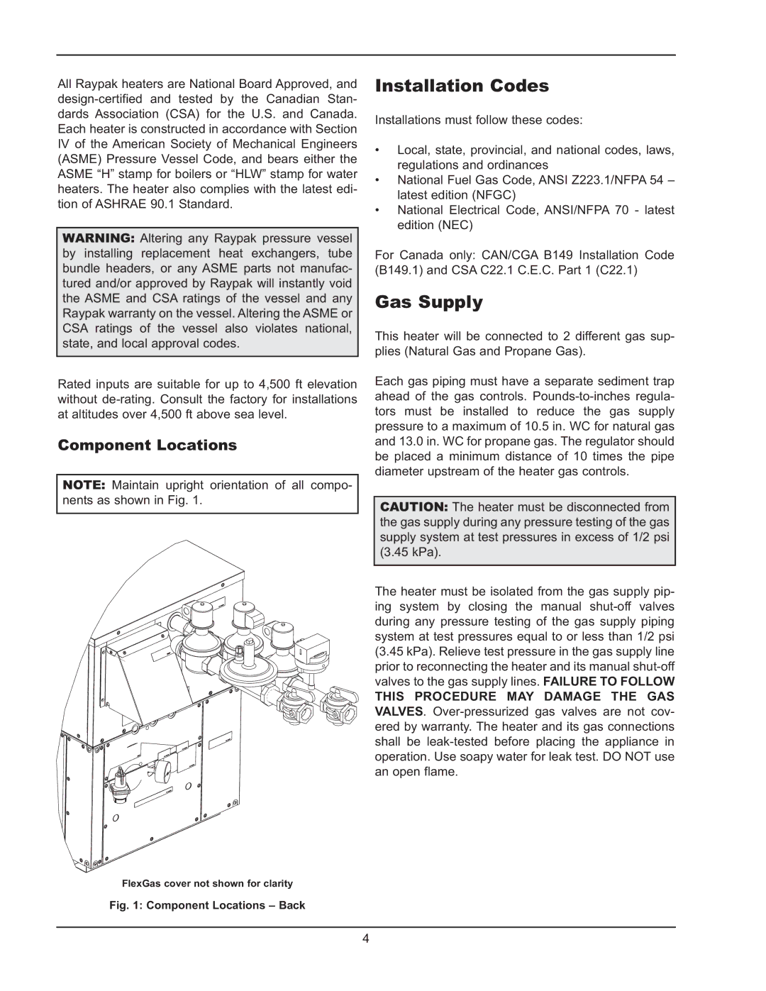
302BD-2342BD specifications
The Raypak 302BD-2342BD is a standout in the realm of commercial water heating, designed to meet the needs of various applications while ensuring efficiency and reliability. Known for its robust construction and state-of-the-art technology, this model is a preferred choice for both residential and commercial users.One of the key features of the Raypak 302BD-2342BD is its dual thermostat functionality. This feature allows for precise temperature control, making it suitable for diverse heating requirements. With a maximum output of 302,000 BTUs, this unit can handle large volumes of water, making it ideal for swimming pools, spas, and other high-demand situations.
The Raypak 302BD-2342BD is also equipped with a highly efficient heat exchanger. Constructed from copper, the heat exchanger provides superior thermal conductivity, allowing for faster heating and improved energy efficiency. This contributes to reduced operating costs, a crucial consideration for commercial applications where budget constraints are paramount.
Another notable characteristic of this model is its compact design. The unit is engineered for easy installation, taking up minimal space while still delivering powerful performance. This aspect is particularly advantageous in commercial settings where space can be a significant limiting factor.
Safety and user-friendly operation are prioritized in the design of the Raypak 302BD-2342BD. It features an integrated digital display, providing users with real-time information about the unit's performance and conditions. Furthermore, the model includes built-in diagnostic features, allowing for easy troubleshooting and maintenance.
The Raypak 302BD-2342BD also boasts advanced flame sensing technology, ensuring a secure and reliable ignition process. This feature enhances safety while promoting efficiency by optimizing combustion levels.
Lastly, the unit is compatible with various fuel types, including natural gas and propane. This versatility ensures that users can select the most suitable fuel source based on availability and cost considerations.
In summary, the Raypak 302BD-2342BD represents the pinnacle of modern water heating technology, boasting features such as dual thermostats, a high-efficiency heat exchanger, a compact design, and advanced safety measures. Its combination of power, efficiency, and versatility positions it as a leader in the market, meeting the heating needs of both residential and commercial users alike.