*
A LIC;NMENT INSTITIJC'fIONS
Equiptnr:nt rcquirccl :
l . Oscilloscopc with calibratcd vcrtical scalc 2, RF Signal gcncrator - capablc of:
a, Oprcratiol fronr 455 KC to 30 MC
b. Attenuation below lpv output
c . Modulation at I KC wich variablc modula - tron pcrccnt.rges
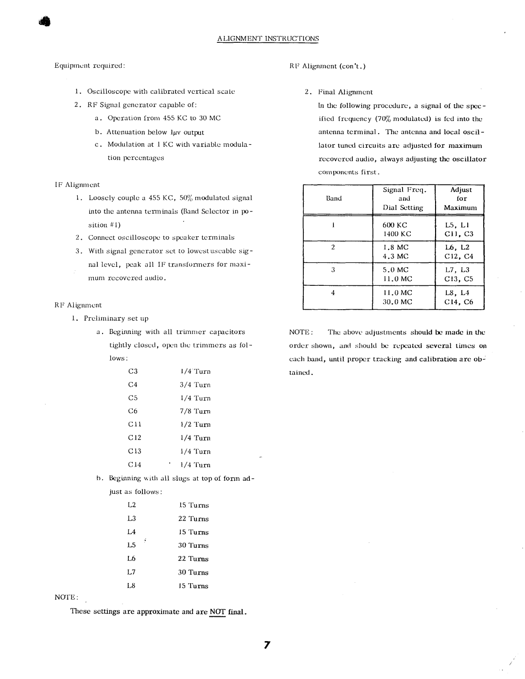
RF Alig'nmcnt (con't . )
Z . Final A - lig'nrncnt
ln
antenna tcrminal. Thc antcnna and local oscil-
Iator tuncd circuits arc adjustcd for maximum rccovcrcd audio, always adjusting thc oscillator cornlxrncnts first .
IF Alignnrent
1 . Looscly couplc a 455 KC, 50/u modulatcct signal into thc antenna temrinals (Bancl Sclector in po-
s i t i o n # l )
2 . Corulcct oscilloscopc to spcaker tcrminals
3 . With signal gcncr . rtor:'sct to lowcstu . scablc sig - nal levcl, 1rcak all IF - transfomrers for nrexi - rnunl recovcred audio .
RF Alignmcnt
l . Prcliminary set up
a, Bcgi,ruringwith all
tightly closcd, o1r:nthc trinrn)crs as fol- Iows:
C3 | I /4 'I'urn | |
C4 | 3/4 Ttrn | |
C5 | l/4 | Tuln |
C6 | 7/8 | Turn |
Crl | ||
Clz | l/4'furn | |
C l 3 | l / 4 ' f u r n | |
C 14 | l,z4 'furn | |
b.llcginnirg $itlr ail slugs at top of fonn ad- just as follotvs:
L2 | l5 Turns |
L3 | 22 Turns |
L4 | l5 Turns |
| 30 Turns |
L6 | 22 Turns |
L7 | 30 Turns |
L8 | 15 'I'urns |
NOE:
These settings are approximate and are NOT final-
Signal Frcq . | Adjust | |
Iland | and | for |
Dial | Sctting | Maximunr |
|
| 600KC | L 5 , L I | |
|
| 1400KC | c l l , | c 3 |
| 2 | I , 8 M C | L6, | L2 |
|
| 4 . 3 M C | ctz, c4 | |
|
| 5 . 0 M C | L7, | L3 |
|
| l r . 0 M c | c 1 3 , c 5 | |
| 4 | l r . 0 M C | L8, L4 | |
|
| 3 0 . 0M C | c 14, c6 | |
NOTE: | The | atrovc adjustrncnts should | bc madc in tlrc | |
ordcr shown, anrl shoukl bc
7