ENGLISH
Connecting to the Gas Valve
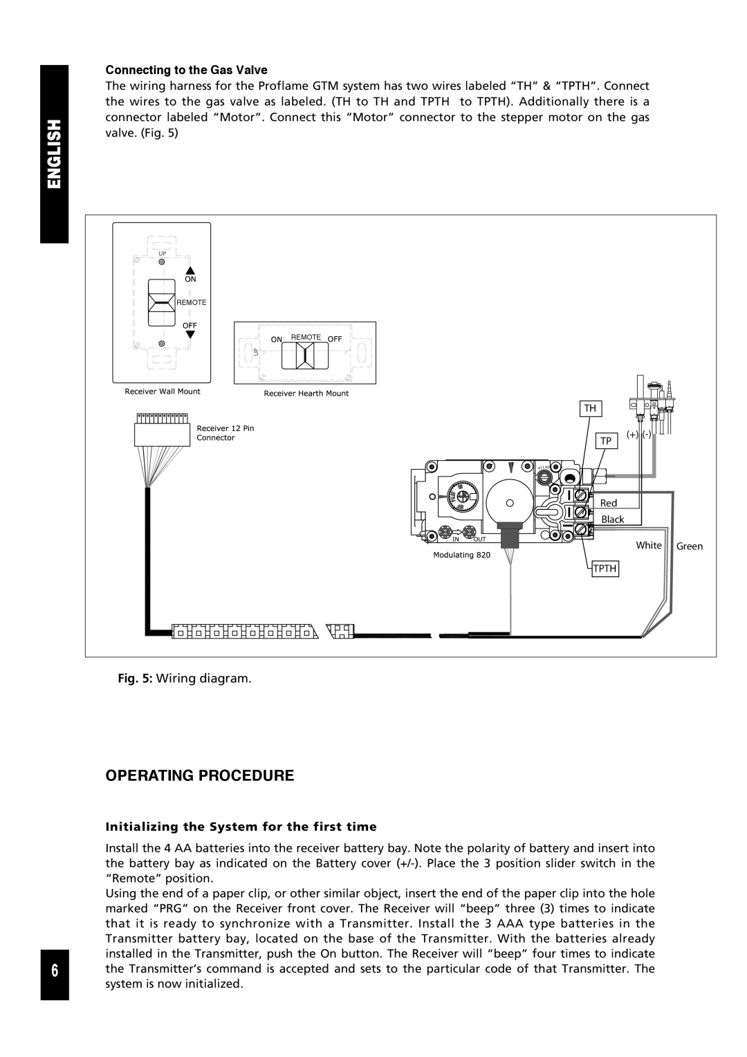
The wiring harness for the Proflame GTM system has two wires labeled “TH” & “TPTH”. Connect the wires to the gas valve as labeled. (TH to TH and TPTH to TPTH). Additionally there is a connector labeled “Motor”. Connect this “Motor” connector to the stepper motor on the gas valve. (Fig. 5)
REMOTE |
|
|
REMOTE |
|
|
TH |
|
|
TP | (+) |
|
|
| |
Red |
|
|
Black |
|
|
| White | Green |
TPTH |
|
|
Fig. 5: Wiring diagram.
OPERATING PROCEDURE
Initializing the System for the first time
Install the 4 AA batteries into the receiver battery bay. Note the polarity of battery and insert into the battery bay as indicated on the Battery cover
Using the end of a paper clip, or other similar object, insert the end of the paper clip into the hole marked “PRG” on the Receiver front cover. The Receiver will “beep” three (3) times to indicate that it is ready to synchronize with a Transmitter. Install the 3 AAA type batteries in the Transmitter battery bay, located on the base of the Transmitter. With the batteries already installed in the Transmitter, push the On button. The Receiver will “beep” four times to indicate
6 the Transmitter’s command is accepted and sets to the particular code of that Transmitter. The system is now initialized.