Manuals
/
Remington
/
Lawn and Garden
/
Pole Saw
Remington
110946-01A
owner manual
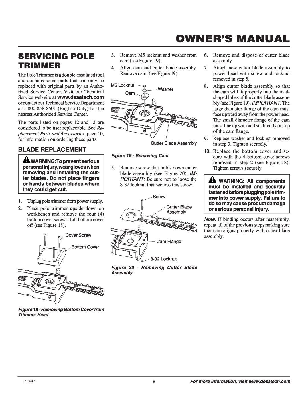
Servicing Pole Trimmer, Blade Replacement
Models:
110946-01A
1
9
44
44
Download
44 pages
43.42 Kb
6
7
8
9
10
11
12
13
Troubleshooting
Parts list
Connecting Extension Cord
Adjusting Pole Length
Blade Replacement
Safety
Technical Service
Solution
Page 9
Image 9
Page 8
Page 10
Page 9
Image 9
Page 8
Page 10
Contents
AXCESS TRIMMER
Electric Pole Trimmer
MODEL 110946-01A
ELECTRIC POLE TRIMMER
SAFETY WARNINGS
BEFORE OPERATING POLE TRIMMER
WHILE OPERATING POLE TRIMMER
UNPACKING
MAINTENANCE AND STORAGE OF POLE TRIMMER
PRODUCT IDENTIFICATION
Continued
CONNECTING EXTENSION CORD
PIVOTING THE POWER HEAD
OPERATING POLE TRIMMER
EXTENSION CORDS
Unlocking the Trigger to Start the Pole Trimmer
STARTING THE POLE TRIMMER
USING THE POLE TRIMMER
ADJUSTING POLE LENGTH
OPERATING POSITIONS
Locking the Pole Trimmer ON
TRIMMING A HEDGE
TROUBLESHOOTING
CLEANING AND MAINTENANCE
OBSERVED FAULT
POSSIBLE CAUSE
SERVICING POLE TRIMMER
BLADE REPLACEMENT
TECHNICAL SERVICE
REPLACEMENT PARTS AND ACCESSORIES
REPAIR SERVICE
WARRANTY SERVICE
PARTS CENTRAL
POLE TRIMMER MODEL 110946-01A
ILLUSTRATED PARTS BREAKDOWN
PARTS LIST
Industries of Canada, Inc
ELECTRIC POLE TRIMMER LIMITED WARRANTY
MANUAL DEL PROPIETARIO
Podadora Eléctrica De Pértiga
MODELO 110946-01A
ADVERTENCIAS DE SEGURIDAD
PODADORA ELÉCTRICA DE PÉRTIGA
ANTES DE OPERAR LA PODADORA DE PÉRTIGA
MIENTRAS OPERE LA PODADORA DE PÉRTIGA
DESEMPAQUE
MANUAL DEL PROPIETARIO
Continuación
MANTENIMIENTO Y ALMACENAJE DE LA PODADORA DE PÉRTIGA
IDENTIFICACIÓN DEL PRODUCTO
OPERACIÓN DE LA PODADORA
GIRO DE LA CABEZA DE POTENCIA
CORDONES DE EXTENSIÓN
CONEXIÓN DEL CORDÓN DE EXTENSIÓN
ARRANQUE DE LA PODADORA DE PÈRTIGA
Desbloqueo del gatillo para arrancar la podadora de pértiga
Bloqueo de la podadora de pértiga en ON encendido
REGULACIÓN DE LA LONGITUD DE LA PÉRTIGA
POSICIONES DE OPERACIÓN
USO DE LA PODADORA DE PÉRTIGA
PODADO DE UN SETO
ANÁLISIS DE AVERÍAS
LIMPIEZA Y MANTENIMIENTO
FALLA OBSERVADA
CAUSA PROBABLE
REEMPLAZO DE LA CUCHILLA
SERVICIO A LA PODADORA DE PÉRTIGA
SERVICIO TÉCNICO
ACCESORIOS Y PIEZAS DE REPUESTO
SERVICIO DE REPARACIÓN
SERVICIO CON GARANTÍA
PODADORA DE PÉRTIGA MODELO 110946-01A
DESARME ILUSTRADO DE LAS PIEZAS
PODADORA ELÉCTRICA DE PIEZAS MODELO 110946-01A
LISTA DE PIEZAS
CENTRAL DE PIEZAS
GARANTÍA LIMITADA DE LA PODADORA ELÉCTRICA DE PÉRTIGA
GUIDE DU PROPRIÉTAIRE
Taille-Haie Électrique À Perche
MODÈLE 117535-01A
CONSIGNES DE SÉCURITÉ
GUIDE DU PROPRIÉTAIRE
AVANT D’UTILISER LE TAILLE-HAIE À PERCHE
UTILISATION DU TAILLE-HAIE À PERCHE
DÉBALLAGE
TAILLE-HAIE ÉLECTRIQUE À PERCHE
Suite
ENTRETIEN ET ENTREPOSAGE DU TAILLE-HAIE À PERCHE
IDENTIFICATION DU PRODUIT
UTILISATION DU TAILLE-HAIE
POUR FAIRE PIVOTER LE MOTEUR
RACCORDEMENT DE LA RALLONGE ÉLECTRIQUE
RALLONGE ÉLECTRIQUE
Verrouillage du taille-haie en position « MARCHE »
DÉMARRAGE DU TAILLE-HAIE À PERCHE
RÉGLAGE DE LA LONGUEUR DE LA PERCHE
POSITIONS DE FONCTIONNEMENT
UTILISATION DU TAILLE-HAIE
TAILLE D’UNE HAIE
NETTOYAGE ET ENTRETIEN
SOLUTION
DÉPANNAGE
PROBLÈME
ENTRETIEN DU TAILLE-HAIE À PERCHE
REMPLACEMENT DES LAMES
SERVICE TECHNIQUE
PIÈCES DE RECHANGE ET ACCESSOIRES
SERVICE DE RÉPARATION
SERVICE SOUS GARANTIE
DÉPÔT DE PIÈCES
TAILLE-HAIE À PERCHE MODÈLE 110946-01A
LISTE ILLUSTRÉE DES PIÈCES
LISTE DE PIÈCES
110939-04 Rev. B 02/06
GARANTIE LIMITÉE DU TAILLE-HAIE ÉLECTRIQUE À PERCHE
Top
Page
Image
Contents