MAINTENANCE
WARNING:
When servicing use only identical RIDGID replacement parts. Use of any other parts may create a hazard or cause product damage.
WARNING:
Always wear safety goggles or safety glasses with side shields during power tool operation or when blowing dust. If operation is dusty, also wear a dust mask.
GENERAL MAINTENANCE
Avoid using solvents when cleaning plastic parts. Most plastics are susceptible to damage from various types of commercial solvents and may be damaged by their use. Use clean cloths to remove dirt, dust, oil, grease, etc.
WARNING:
Do not at any time let brake fluids, gasoline,
Electric tools used on fiberglass material, wallboard, spack- ling compounds, or plaster are subject to accelerated wear and possible premature failure because the fiberglass chips and grindings are highly abrasive to bearings, brushes, com- mutators, etc. Consequently, we do not recommended using this tool for extended work on these types of materials. How- ever, if you do work with any of these materials, it is extremely important to clean the tool using compressed air.
LUBRICATION
All of the bearings in this tool are lubricated with a sufficient amount of high grade lubricant for the life of the unit under normal operating conditions. Therefore, no further lubrication is required.
REPLACING THE GUARD
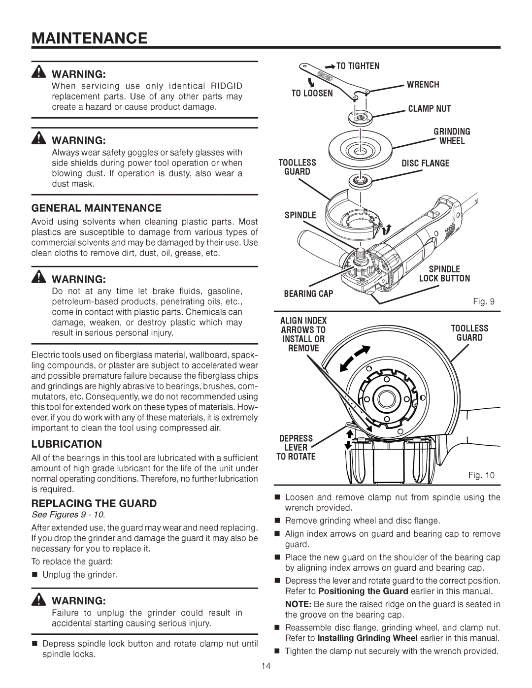
See Figures 9 - 10.
After extended use, the guard may wear and need replacing. If you drop the grinder and damage the guard it may also be necessary for you to replace it.
To replace the guard: � Unplug the grinder.
WARNING:
Failure to unplug the grinder could result in accidental starting causing serious injury.
� Depress spindle lock button and rotate clamp nut until spindle locks.
![]() TO TIGHTEN
TO TIGHTEN
WRENCH
TO LOOSEN
CLAMP NUT
GRINDING
![]() WHEEL
WHEEL
TOOLLESS | DISC FLANGE |
GUARD |
|
SPINDLE
SPINDLE
LOCK BUTTON
BEARING CAP
Fig. 9
ALIGN INDEX | TOOLLESS |
ARROWS TO | |
INSTALL OR | GUARD |
REMOVE |
|
DEPRESS
LEVER
TO ROTATE
Fig. 10
� Loosen and remove clamp nut from spindle using the wrench provided.
� Remove grinding wheel and disc flange.
� Align index arrows on guard and bearing cap to remove guard.
� Place the new guard on the shoulder of the bearing cap by aligning index arrows on guard and bearing cap.
� Depress the lever and rotate guard to the correct position. Refer to Positioning the Guard earlier in this manual.
NOTE: Be sure the raised ridge on the guard is seated in the groove on the bearing cap.
� Reassemble disc flange, grinding wheel, and clamp nut. Refer to Installing Grinding Wheel earlier in this manual.
� Tighten the clamp nut securely with the wrench provided.
14
