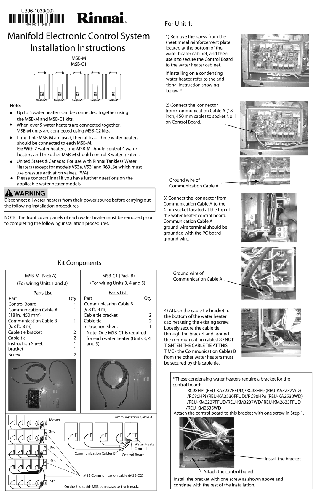
Rinnai MSB-M installation instructions Kit Components, For Unit, Installation Instructions

Models: MSB-M MSB-C1

1 2
Download 2 pages 30.99 Kb
Page 1
Image 1
Manifold Electronic Control System

U306-1030(00)

070 00012 32035 9

Manifold Electronic Control System

Installation Instructions

MSB-M

MSB-C1

Note:

Up to 5 water heaters can be connected together using the MSB-M and MSB-C1 kits.

When over 5 water heaters are connected together, MSB-M units are connected using MSB-C2 kits.

If multiple MSB-M are used, then at least three water heaters should be connected to each MSB-M.

Ex: With 7 water heaters, one MSB-M should control 4 water heaters and the other MSB-M should control 3 water heaters.

United States & Canada: For use with Rinnai Tankless Water Heaters (except for models V53e, V53i and R63LSe which must use pressure activation valves, PVA).

Please contact Rinnai if you have further questions on the applicable water heater models.

Installation InstructionsWARNING

Disconnect all water heaters from their power source before carrying out the following installation procedures.

NOTE: The front cover panels of each water heater must be removed prior to completing the following installation procedures.

Kit Components


MSB-M (Pack A)


MSB-C1 (Pack B)


(For wiring Units 1 and 2)


(For wiring Units 3, 4 and 5)


Parts List


Parts List


Part

Qty

Part


Qty


Control Board

1


Communication Cable B

1


Communication Cable A

1


(9.8 ft, 3 m)


(18 in, 450 mm)


Cable tie bracket


2


Communication Cable B

1


Cable tie


2


(9.8 ft, 3 m)


Instruction Sheet


1


Cable tie bracket

2


Note: One MSB-C1 is required


Cable tie

2


for each water heater (Units 3, 4,


Instruction Sheet

1


and 5)


bracket

1


Screw

2


Master


Communication Cable A


2nd


3rd


Water Heater


Control


4th

Communication Cables B

Control Board


MSB Communication cable (MSB-C2)


5th


On the 2nd to 5th MSB boards, set to 1 unit ready.


For Unit 1:

1)Remove the screw from the sheet metal reinforcement plate located at the bottom of the water heater cabinet, and then use it to secure the Control Board to the water heater cabinet.

If installing on a condensing water heater, refer to the addi- tional instruction showing below. *

2) Connect the connector

from Communication Cable A (18 inch, 450 mm cable) to socket No. 1 on Control Board.

Ground wire of

Communication Cable A

3)Connect the connector from Communication Cable A to the

4-pin socket located at the top of the water heater control board. Communication Cable A ground wire terminal should be grounded with the PC board ground wire.

Ground wire of

Communication Cable A

4)Attach the cable tie bracket to the bottom of the water heater cabinet using the existing screw. Loosely secure the cable tie through the bracket and around the communication cable. DO NOT TIGHTEN THE CABLE TIE AT THIS TIME - the Communication Cables B from the other water heaters must be secured by this cable tie.

*These condensing water heaters require a bracket for the control board:

RC98HPi (REU-KA3237FFUD)/RC98HPe (REU-KA3237WD) /RC80HPi (REU-KA2530FFUD)/RC80HPe (REU-KA2530WD)

/REU-KM3237FFUD/REU-KM3237WD/ REU-KM2635FFUD

/REU-KM2635WD

Attach the control board to this bracket with one screw in Step 1.

Install the bracket

Attach the control board

Install the bracket with one screw as shown above and continue with the rest of the installation.

Page 1
Image 1
Rinnai MSB-M, MSB-C1 installation instructions Kit Components, For Unit, Manifold Electronic Control System