Panel Descriptions
Front
fig.
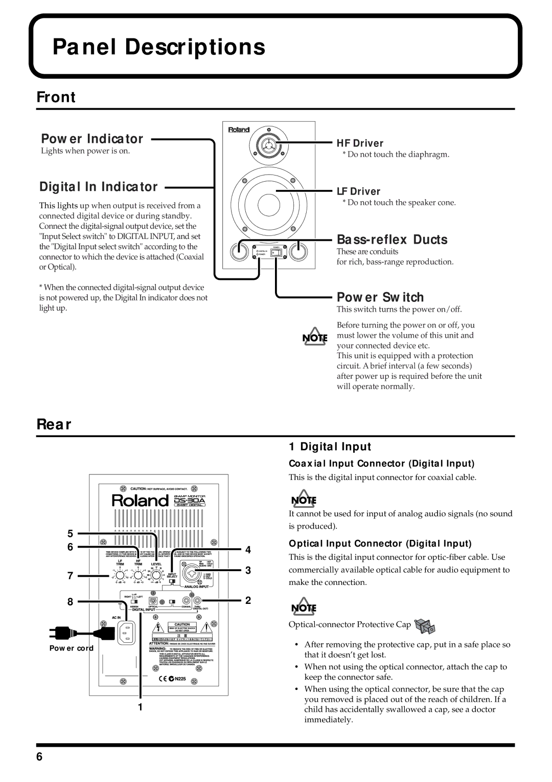
Power Indicator
Lights when power is on.
Digital In Indicator
This lights up when output is received from a connected digital device or during standby. Connect the
*When the connected
Rear
HF Driver
* Do not touch the diaphragm.
LF Driver
* Do not touch the speaker cone.
These are conduits
for rich,
Power Switch
This switch turns the power on/off.
Before turning the power on or off, you must lower the volume of this unit and your connected device etc.
This unit is equipped with a protection circuit. A brief interval (a few seconds) after power up is required before the unit will operate normally.
fig.
5
6![]()
7 |
8 |
Power cord
1
4
3
2
1 Digital Input
Coaxial Input Connector (Digital Input)
This is the digital input connector for coaxial cable.
It cannot be used for input of analog audio signals (no sound
is produced).
Optical Input Connector (Digital Input)
This is the digital input connector for
commercially available optical cable for audio equipment to
make the connection.
![]()
•After removing the protective cap, put in a safe place so that it doesn’t get lost.
•When not using the optical connector, attach the cap to keep the connector safe.
•When using the optical connector, be sure that the cap you removed is placed out of the reach of children. If a child has accidentally swallowed a cap, see a doctor immediately.
6
