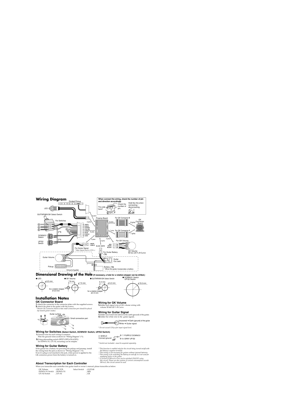
Wiring Diagram
Divided Pickup
LED ![]()
GUITAR/MIX/GK Select Switch
8 pins
When connect the wiring, check the number of pin and direction accordingly
| Check the | Hold like this when | |
| connecting / | ||
This side | number of | ||
disconnecting. | |||
pin. | |||
here!! |
| ||
|
|
| Preamp Board |
| For GK |
| For Switches |
| GK |
| 8 pins | 8 pins Connector | |
| 2 pins | ||
4 | WHITE |
| Board |
|
|
5 |
|
| SHIELD |
|
|
|
| 4 | ORANGE |
|
|
| |
6 |
| YELLOW |
| 7 pins For GK | ||
(*1) | 5 | GREEN |
| |||
| 8 pins | |||||
| BLUE |
|
| |||
| 6 |
| 7 pins | |||
DOWN/S1 |
| PURPLE |
|
| ||
|
| GRAY |
|
|
| |
Switch |
|
|
|
| 3 pins |
|
| (*1) |
|
| 2 pins |
| |
|
|
| For GK Volume | |||
UP/S2 |
|
|
| 2 pins | ||
|
|
|
|
|
| |
Switch |
|
|
| WHITE | RED | 3 |
|
|
|
| SHIELD | 2 | |
|
|
|
| WHITE | ||
|
|
|
| BLACK WHITE | ||
|
|
| For Guitar Signal |
| BLACK | 1 |
|
|
|
|
| ||
|
|
| * Max Input level is |
| GK Volume | |
|
|
|
| For Guitar Battery | 50 kΩ ±20 % B Curve | |
|
| 1 |
| (*2) |
| |
Guitar Volume |
|
|
|
|
| |
| 2 |
|
| Guitar |
| |
|
|
|
|
| ||
|
| 3 |
|
|
| |
|
|
|
| Out Jack |
| |
|
|
|
|
|
| |
|
|
|
| + – |
|
|
Pickup
Circuit of guitar
Buttery (*2)
* When the guitar incorporates a battery
Dimensional Drawing of the Hole (If necessary, a hole for a
● LED | ● GK Volume | ● GUITAR/MIX/GK Select Switch | ● DOWN/S1 Switch | ||||||||||||
| UP/S2 Switch | ||||||||||||||
| 8.5 mm |
| 7.8 mm |
| 6.4 mm |
|
|
|
|
|
| ||||
|
| for a |
|
| 7.5 mm |
|
|
|
| 6.2 mm |
| 15.0 mm | |||
|
|
|
|
|
|
|
| ||||||||
|
|
|
|
|
|
|
|
|
|
|
|
|
|
| |
|
|
|
|
|
|
|
|
|
|
|
|
|
|
| |
|
|
|
|
|
|
|
|
|
|
|
|
|
|
| |
|
| 3.0 mm |
|
|
|
| for a |
|
|
|
|
|
| ||
|
|
|
|
|
|
|
|
|
| ||||||
|
|
|
|
|
|
| 2.4 mm |
|
|
|
|
|
| ||
Installation Notes
GK Connector Board
1.Attach the connector to the connector plate with the supplied screws.
2.Attach the plate to the guitar with the screws.
*Mount GK Connector board so that small connection port should be placed top toward guitar surface.
Guitar surface
![]() Small connection port
Small connection port
Wiring for GK Volume
1.Solder each signal wire of GK volume wiring with volume 50 kΩ ±20 % B Curve.
Wiring for Guitar Signal
1.Solder uncovered wire (silver) to the earth (ground) of the guitar.
2.Solder the white wire to the guitar signals.
Uncovered ➔ Earth (ground) of the guitar
White ➔ Guitar signal
* Do not exceed
Wiring for Switches (Select Switch, DOWN/S1 Switch, UP/S2 Switch)
1.Ground wire for each wiring is common.
Wire the ground wires as shown in “Wiring Diagram” (*1).
2.Using rebounding switch (SPDT
2: SHIELD | 7: PURPLE DOWN/S1 |
| |
Connect ground | 8: GRAY UP/S2 |
|
* Switch not
Wiring for Guitar Battery
If the guitar has a battery for powering the pickup and preamp, install the wiring from the jack as shown in “Wiring Diagram” (*2).
Even if a plug is not inserted in the jack, when power is applied to the GK connector, power from the battery is turned on.
About Transcription for Each Controller
*This function is enabled only for the circuit being turned on/off with the battery’s negative terminal.
*This wiring is not necessary for guitars without internal batteries.
*This wiring is for switching the battery on and off; it is not used for supplying power to the guitar.
*A current of 500 mA or less can be switched ON/OFF using
this circuit. Please use due caution; if current consumption exceeds 500 mA, this circuit cannot be used.
When you transcribe each controller into guitar itself or owner’s manual, please transcribe as below:
GK Volume | ...GK VOL | Select Switch ...GUITAR |
DOWN/S1 Switch | ...DOWN/S1 | ...MIX |
UP/S2 Switch | ...UP/S2 | ...GK |