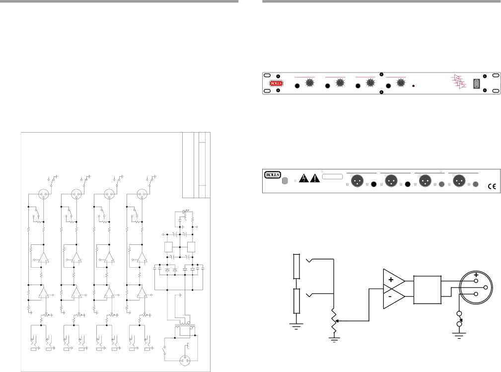
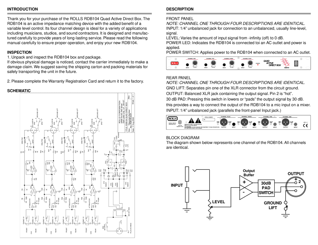
RDB104 specifications
The Rolls RDB104 is a high-performance diesel generator that has gained recognition in the power generation industry for its robust design, efficiency, and reliability. Specifically engineered for industrial applications, this model is widely used in construction sites, manufacturing facilities, and emergency backup power situations due to its versatility and durability.One of the main features of the Rolls RDB104 is its powerful engine, which is capable of delivering an impressive output that ranges from 100 to 250 kVA. This makes it suitable for a variety of load requirements, whether it is supplying power for heavy machinery or running multiple appliances simultaneously. The generator's engine is not only powerful but also designed for fuel efficiency, helping to lower operating costs over time.
In terms of technologies, the Rolls RDB104 is equipped with advanced electronic control systems that optimize performance and enhance efficiency. The generator features an automatic voltage regulator (AVR) that ensures stable voltage output, providing consistent power quality essential for sensitive electronic equipment. Additionally, the unit employs a sophisticated cooling system that prevents overheating, prolonging the engine's lifespan and maintaining optimal performance under heavy loads.
Another significant characteristic of the RDB104 is its compact and sturdy design. Constructed with high-quality materials, the generator is built to withstand harsh environmental conditions, making it an ideal choice for outdoor applications. The enclosure is soundproofed, ensuring quiet operation, which is particularly beneficial in urban settings or noise-sensitive environments.
Moreover, the Rolls RDB104 is designed for ease of maintenance, with accessible service points and simple access to components. Routine maintenance is simplified, helping users to keep the generator in optimal condition with minimal effort. It also comes equipped with safety features such as low oil pressure shutdown, overload protection, and emergency stop functions, which enhance the safety of operation.
In conclusion, the Rolls RDB104 combines power, efficiency, and durability, making it an outstanding choice for businesses and individuals needing reliable backup power or continuous operation in demanding conditions. Its advanced technologies, user-friendly design, and robust construction make it a leader in the diesel generator market, satisfying diverse power generation needs across various sectors.