INTRODUCTION
Thank your for your purchase of the Rolls RM203x Stereo Mic\Line Mixer. The RM203x is a
INSPECTION/WARRANTY
1. Unpack and inspect the RM203x box and package.
Your RM203x was carefully packed at the factory in a protective carton. Nonetheless, be sure to examine the unit and the carton for any signs of damage that may have occurred during shipping. If obvious physical damage is noticed, contact the carrier immediately to make a damage claim. We suggest saving the shipping carton and packing materials for safely transporting the unit in the future.
2.Please visit our website at www.rolls.com and click on the Register Your Warranty Here text. Fill out the warranty information to ensure coverage of your new RA62b. If you do not have access to the internet, or do not wish to register your warranty online, complete the Warranty Registration Card and return it to the factory.
DESCRIPTION
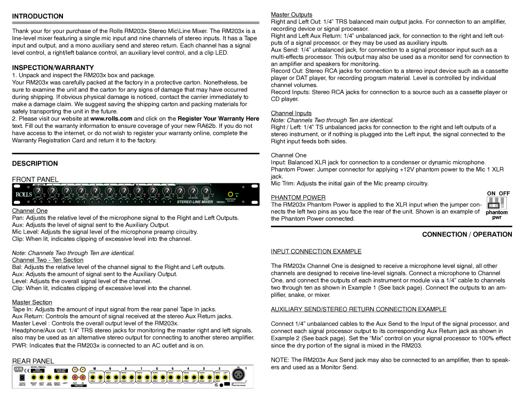
FRONT PANEL
Channel One
Pan: Adjusts the relative level of the microphone signal to the Right and Left Outputs.
Aux: Adjusts the level of signal sent to the Auxiliary Output.
Mic Level: Adjusts the signal level of the microphone preamp circuitry.
Clip: When lit, indicates clipping of excessive level into the channel.
Note: Channels Two through Ten are identical.
Channel Two - Ten Section
Bal: Adjusts the relative level of the channel signal to the Right and Left outputs.
Aux: Adjusts the amount of signal sent to the Auxiliary Output.
Level: Adjusts the overall signal level of the channel.
Clip: When lit, indicates clipping of excessive level into the channel.
Master Section
Tape In: Adjusts the amount of input signal from the rear panel Tape In jacks.
Aux Return: Controls the amount of signal received at the stereo Aux Return jacks.
Master Level : Controls the overall output level of the RM203x.
Headphone/Aux out: 1/4” TRS stereo jacks for monitoring the master right and left signals, also may be used as an alternative stereo output for connecting to another stereo amplifier. PWR: Indicates that the RM203x is connected to an AC outlet and is on.
REAR PANEL
Master Outputs
Right and Left Out: 1/4” TRS balanced main output jacks. For connection to an amplifier, recording device or signal processor.
Right and Left Aux Return: 1/4” unbalanced jack, for connection to the right and left out- puts of a signal processor, or they may be used as auxiliary inputs.
Aux Send: 1/4” unbalanced jack, for connection to a signal processor input such as a
Record Out: Stereo RCA jacks for connection to a stereo input device such as a cassette player or DAT player, for recording program material. Level is controlled by individual channel volumes.
Record Inputs: Stereo RCA jacks for connection to a source such as a cassette player or CD player.
Channel Inputs
Note: Channels Two through Ten are identical.
Right / Left: 1/4” TS unbalanced jacks for connection to the right and left outputs of a stereo instrument, or if nothing is plugged into the Left input, the signal connected to the Right input feeds both sides.
Channel One
Input: Balanced XLR jack for connection to a condenser or dynamic microphone.
Phantom Power: Jumper connector for applying +12V phantom power to the Mic 1 XLR jack.
Mic Trim: Adjusts the initial gain of the Mic preamp circuitry.
PHANTOM POWER | ON OFF |
| |
The RM203x Phantom Power is applied to the XLR input when the jumper con- |
|
nects the left two pins as you face the rear of the unit. Shown is an example of | phantom |
the Phantom Power connected. | pwr |
CONNECTION / OPERATION
INPUT CONNECTION EXAMPLE
The RM203x Channel One is designed to receive a microphone level signal, all other channels are designed to receive
AUXILIARY SEND/STEREO RETURN CONNECTION EXAMPLE
Connect 1/4” unbalanced cables to the Aux Send to the Input of the signal processor, and connect each signal processor output to its corresponding Aux Return jack as shown in Example 2 (See back page). Set the “Mix” control on your signal processor to 100% effect since the dry portion of the signal is mixed in the RM203.
NOTE: The RM203x Aux Send jack may also be connected to an amplifier, then to speak- ers and used as a Monitor Send.