SPECIFICATIONS
Input Impedance: | 600 W balanced | |
|
| 50K W unbalanced (1/4") |
Output Impedance: | 50 W TRS Balanced | |
Max Input Level: | ||
|
| +18 dBV 1/4" |
Phase Shift: |
| < 10 deg. 20 Hz - 20 kHz |
Phantom Power: | 36 V DC | |
Input Connectors: | XLR and 1/4" | |
Outputs: |
| 1/4" main balanced +17 dB max |
|
| 1/4" monitor +17 dB max |
|
| 1/4" FX send |
Max Gain: | (Mains) | 60 dB mic |
|
| 26 dB line |
| (Monitor) | 55 dB |
Tone controls: |
| 20 dB treb, bass cut/boost, 400 Hz center |
Max S/N Ratio: |
| 106 dB |
THD |
| < .003% |
IMD (SMPTE) |
| < .003% |
CMRR |
| 52 dB |
Power |
| 120 VAC |
Weight: |
| 7 lbs (3KG) |
Size: |
| 19" x 1.75" x 6.5" (48cm x 4.5cm x 17cm) |
NOTES:___________________________________________________________
PAN: Adjusts the amount of relative signal to the Right, Left or both Main Out jacks.
FX SEND: Controls the amount of signal
MASTER CONTROLS
FX RETURN: Adjusts the amount of signal coming back into the FX Return jack.
MASTER VOLUME, RIGHT - LEFT: Controls the amount of signal sent out the main Right and Left Output jacks, and sets the overall signal level except for the Monitor Send jack.
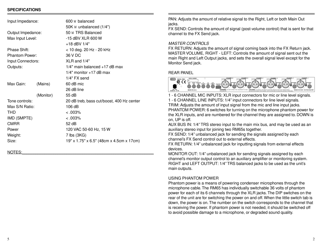
REAR PANEL
MODEL RM65 | SERIAL NUMBER |
|
|
| CHANNEL 6 | CHANNEL 5 |
| CHANNEL 4 | CHANNEL 3 | CHANNEL 2 |
| CHANNEL 1 | ||
|
|
|
|
|
| MIC | MIC |
| MIC | MIC | MIC |
| MIC | |
| 65- |
|
|
|
|
|
|
| ||||||
|
|
|
|
|
|
|
|
|
|
|
|
|
| |
| LEFT | RIGHT | MONITOR | FX | FX | AUX | TRIM LINE | TRIM | LINE | TRIM LINE | TRIM LINE | TRIM | LINE | TRIM LINE |
C US | OUT | OUT | OUT | RETURN | SEND | BUSS IN | PHANTOM |
|
|
|
|
|
|
|
|
|
|
|
|
|
| POWER |
|
|
|
|
|
|
|
120 VAC | MADE IN U.S.A. |
|
|
| WARNING: DO NOT EXPOSE THIS EQUIPMENT TO RAIN | CAUTION: TO REDUCE THE RISK OF ELECTRIC SHOCK DO NOT NOT REMOVE BACK. | RISQUE DE CHOC - NE PAS ENLEVER | |||||||
50/60 Hz 15 VA |
|
|
|
|
|
| OR MOISTURE. |
| NO USER SERVICABLE PARTS INSIDE. REFER SERVICING TO QUALIFIED SERVICE PERSONNEL. |
|
| |||
1 - 6 CHANNEL MIC INPUTS: XLR input connectors for mic or line level signals.
1 - 6 CHANNEL LINE INPUTS: 1/4” input connectors for line level signals.
TRIM: Adjusts the amount of input signal from the mic and line input jacks.
PHANTOM POWER: 6 switches for turning on the microphone phantom power for the XLR inputs, and are numbered for the channel they are assigned to. DOWN is on, UP is off.
AUX BUS IN: 1/4” TRS stereo input to the main mix bus, and may be used as an auxiliary stereo input for joining two RM65s together.
FX SEND: 1/4” unbalanced jack for sending the signals assigned by each channel’s FX Send control out to external effects.
FX RETURN: 1/4” unbalanced jack for inputting signals from external effects devices.
MONITOR OUT: 1/4” unbalanced jack for sending signals assigned by each channel’s monitor output control to an auxiliary amplifier or monitoring system. RIGHT and LEFT OUTPUT: 1/4” TRS balanced jacks to be used as the unit’s main outputs.
USING PHANTOM POWER
Phantom power is a means of powering condenser microphones through the microphone cable. The RM65 has individually switchable 36 volts of phantom power for each of its 6 channels through the XLR jacks. The DIP switches on the rear of the unit are for switching the power on and off. When the little switch tab is down, the power is on. The number on the switch corresponds to the channel that is receiving the power. If phantom power is not needed, it should be switched off to avoid possible damage to a microphone, or degraded sound quality.
5 | 2 |