DESCRIPTION
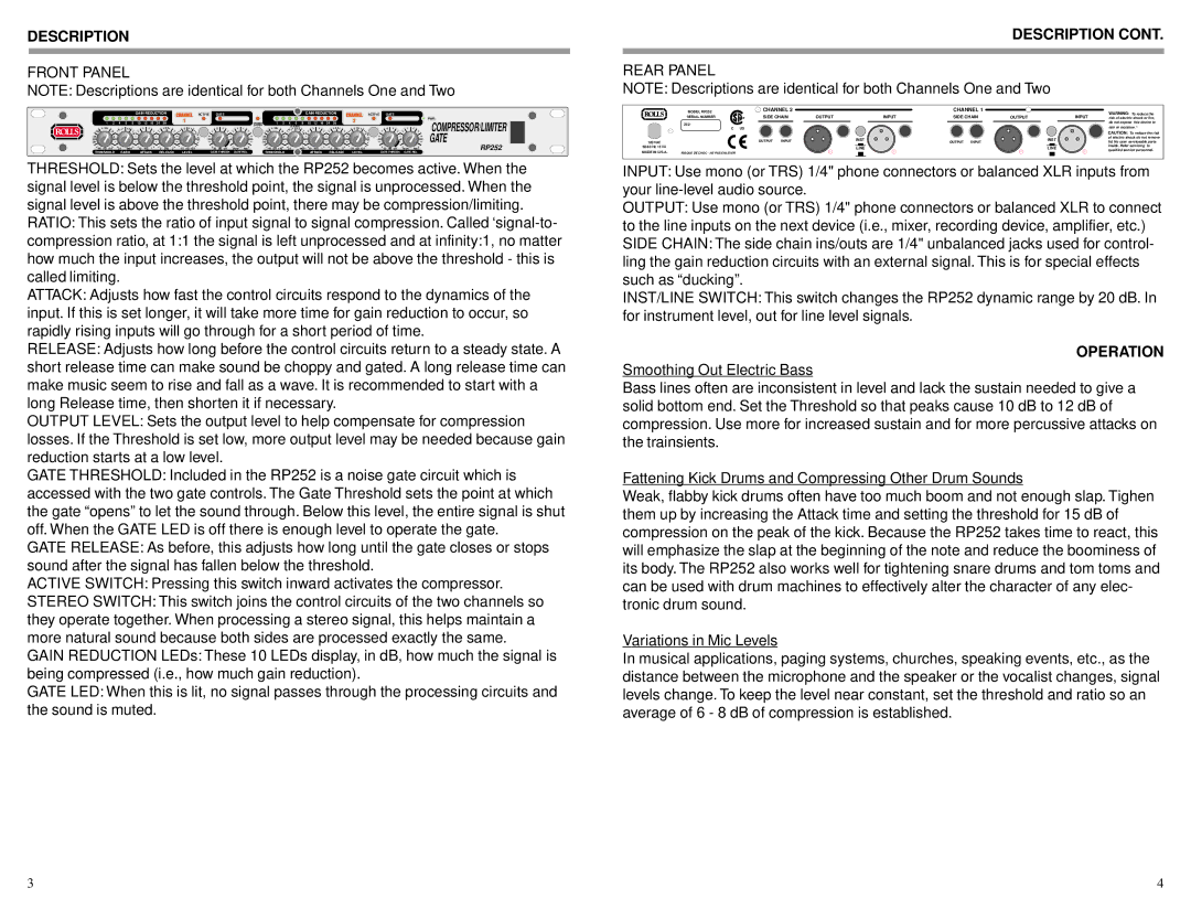
FRONT PANEL
NOTE: Descriptions are identical for both Channels One and Two
|
|
|
|
|
| GAIN REDUCTION |
|
| ACTIVE | GATE |
|
|
|
|
|
|
| GAIN REDUCTION |
|
|
| ACTIVE | GATE |
|
|
| |||||||||
|
|
|
|
|
|
|
|
|
|
|
|
|
|
|
|
|
|
|
|
|
|
|
|
|
|
|
|
|
|
|
|
|
|
| PWR |
1 | 2 | 4 | 6 | 8 | 10 | 12 | 18 | 24 | 38 |
|
| +10 |
|
|
| 1 | 2 | 4 | 6 | 8 | 10 | 12 | 18 | 24 | 38 |
|
|
| +10 |
|
|
| COMPRESSOR/LIMITER | ||
|
|
| 9:1 |
|
|
|
|
|
|
|
|
|
| RATIO | 9:1 |
|
|
|
|
|
|
|
|
|
|
| |||||||||
|
|
| 7:1 |
|
|
|
|
| 2.5 |
|
| 0 | 0 |
|
| STEREO |
|
|
|
|
|
| 2.5 |
|
| 0 |
| 0 |
|
|
| ||||
|
| 4:1 |
|
|
|
|
|
|
|
|
|
|
| 4:1 | 7:1 |
|
|
|
|
|
|
|
|
|
| GATE | |||||||||
| 0 |
|
|
|
|
|
|
|
|
|
|
|
|
|
|
| 0 |
|
|
|
|
|
|
|
|
|
|
|
|
|
|
| |||
|
|
|
|
|
|
|
|
|
|
|
| +4 |
|
|
|
|
|
|
|
|
|
|
|
|
|
|
| +4 |
|
|
| ||||
|
|
|
|
|
|
|
|
|
|
|
|
|
|
|
|
|
|
|
|
|
|
|
|
|
|
|
|
|
|
|
|
|
| ||
dB +10 | 2:1 |
| :1 | 10 | mS | 1 | 5 | Sec | .5 | dB +20 | slow | fast | dB +10 | 2:1 |
| :1 | 10 | mS | 1 | 5 | Sec | .5 | dB +20 |
| slow | fast | RP252 | ||||||||
THRESHOLD | RATIO |
| ATTACK | RELEASE | LEVEL | GATE THRESH | GATE REL | THRESHOLD |
|
|
| ATTACK | RELEASE | LEVEL |
| GATE THRESH | GATE REL |
| |||||||||||||||||
THRESHOLD: Sets the level at which the RP252 becomes active. When the signal level is below the threshold point, the signal is unprocessed. When the signal level is above the threshold point, there may be compression/limiting.
RATIO: This sets the ratio of input signal to signal compression. Called
ATTACK: Adjusts how fast the control circuits respond to the dynamics of the input. If this is set longer, it will take more time for gain reduction to occur, so rapidly rising inputs will go through for a short period of time.
RELEASE: Adjusts how long before the control circuits return to a steady state. A short release time can make sound be choppy and gated. A long release time can make music seem to rise and fall as a wave. It is recommended to start with a long Release time, then shorten it if necessary.
OUTPUT LEVEL: Sets the output level to help compensate for compression losses. If the Threshold is set low, more output level may be needed because gain reduction starts at a low level.
GATE THRESHOLD: Included in the RP252 is a noise gate circuit which is accessed with the two gate controls. The Gate Threshold sets the point at which the gate “opens” to let the sound through. Below this level, the entire signal is shut off. When the GATE LED is off there is enough level to operate the gate.
GATE RELEASE: As before, this adjusts how long until the gate closes or stops sound after the signal has fallen below the threshold.
ACTIVE SWITCH: Pressing this switch inward activates the compressor.
STEREO SWITCH: This switch joins the control circuits of the two channels so they operate together. When processing a stereo signal, this helps maintain a more natural sound because both sides are processed exactly the same.
GAIN REDUCTION LEDs: These 10 LEDs display, in dB, how much the signal is being compressed (i.e., how much gain reduction).
GATE LED: When this is lit, no signal passes through the processing circuits and the sound is muted.
DESCRIPTION CONT.
REAR PANEL
NOTE: Descriptions are identical for both Channels One and Two
| MODEL RP252 | CHANNEL 2 |
|
| CHANNEL 1 |
|
| WARNING: To reduce the | |
| SERIAL NUMBER | SIDE CHAIN | OUTPUT | INPUT | SIDE CHAIN | OUTPUT | INPUT | ||
| risk of electric shock or fire, | ||||||||
| 252- |
|
|
|
|
|
|
| do not expose this device to |
|
|
|
|
|
|
|
| rain or moisture. : | |
| C | US |
|
|
|
|
|
| |
|
|
|
|
|
|
|
|
| CAUTION: To reduce the risk |
|
| OUTPUT | INPUT |
| INST |
|
| INST | of electric shock do not remove |
120 VAC |
|
| OUTPUT INPUT |
| lid. No user serviceable parts | ||||
50/60 Hz 15 VA |
|
|
|
| LINE |
|
| LINE | inside. Refer servicing to |
MADE IN U.S.A. | RISQUE DE CHOC - NE PAS ENLEVER |
|
|
|
|
|
|
| qualified service personnel. |
|
|
|
|
|
|
|
| ||
INPUT: Use mono (or TRS) 1/4" phone connectors or balanced XLR inputs from your
OUTPUT: Use mono (or TRS) 1/4" phone connectors or balanced XLR to connect to the line inputs on the next device (i.e., mixer, recording device, amplifier, etc.) SIDE CHAIN: The side chain ins/outs are 1/4" unbalanced jacks used for control- ling the gain reduction circuits with an external signal. This is for special effects such as “ducking”.
INST/LINE SWITCH: This switch changes the RP252 dynamic range by 20 dB. In for instrument level, out for line level signals.
OPERATION
Smoothing Out Electric Bass
Bass lines often are inconsistent in level and lack the sustain needed to give a solid bottom end. Set the Threshold so that peaks cause 10 dB to 12 dB of compression. Use more for increased sustain and for more percussive attacks on the trainsients.
Fattening Kick Drums and Compressing Other Drum Sounds
Weak, flabby kick drums often have too much boom and not enough slap. Tighen them up by increasing the Attack time and setting the threshold for 15 dB of compression on the peak of the kick. Because the RP252 takes time to react, this will emphasize the slap at the beginning of the note and reduce the boominess of its body. The RP252 also works well for tightening snare drums and tom toms and can be used with drum machines to effectively alter the character of any elec- tronic drum sound.
Variations in Mic Levels
In musical applications, paging systems, churches, speaking events, etc., as the distance between the microphone and the speaker or the vocalist changes, signal levels change. To keep the level near constant, set the threshold and ratio so an average of 6 - 8 dB of compression is established.
3 | 4 |