TROUBLESHOOTING
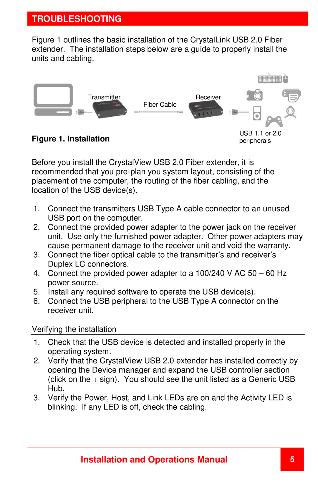
Figure 1 outlines the basic installation of the CrystalLink USB 2.0 Fiber extender. The installation steps below are a guide to properly install the units and cabling.
Transmitter | Receiver |
| Fiber Cable |
Figure 1. Installation | USB 1.1 or 2.0 |
peripherals |
Before you install the CrystalView USB 2.0 Fiber extender, it is recommended that you
1.Connect the transmitters USB Type A cable connector to an unused USB port on the computer.
2.Connect the provided power adapter to the power jack on the receiver unit. Use only the furnished power adapter. Other power adapters may cause permanent damage to the receiver unit and void the warranty.
3.Connect the fiber optical cable to the transmitter’s and receiver’s Duplex LC connectors.
4.Connect the provided power adapter to a 100/240 V AC 50 – 60 Hz power source.
5.Install any required software to operate the USB device(s).
6.Connect the USB peripheral to the USB Type A connector on the receiver unit.
Verifying the installation
1.Check that the USB device is detected and installed properly in the operating system.
2.Verify that the CrystalView USB 2.0 extender has installed correctly by opening the Device manager and expand the USB controller section (click on the + sign). You should see the unit listed as a Generic USB Hub.
3.Verify the Power, Host, and Link LEDs are on and the Activity LED is blinking. If any LED is off, check the cabling.
Installation and Operations Manual
5