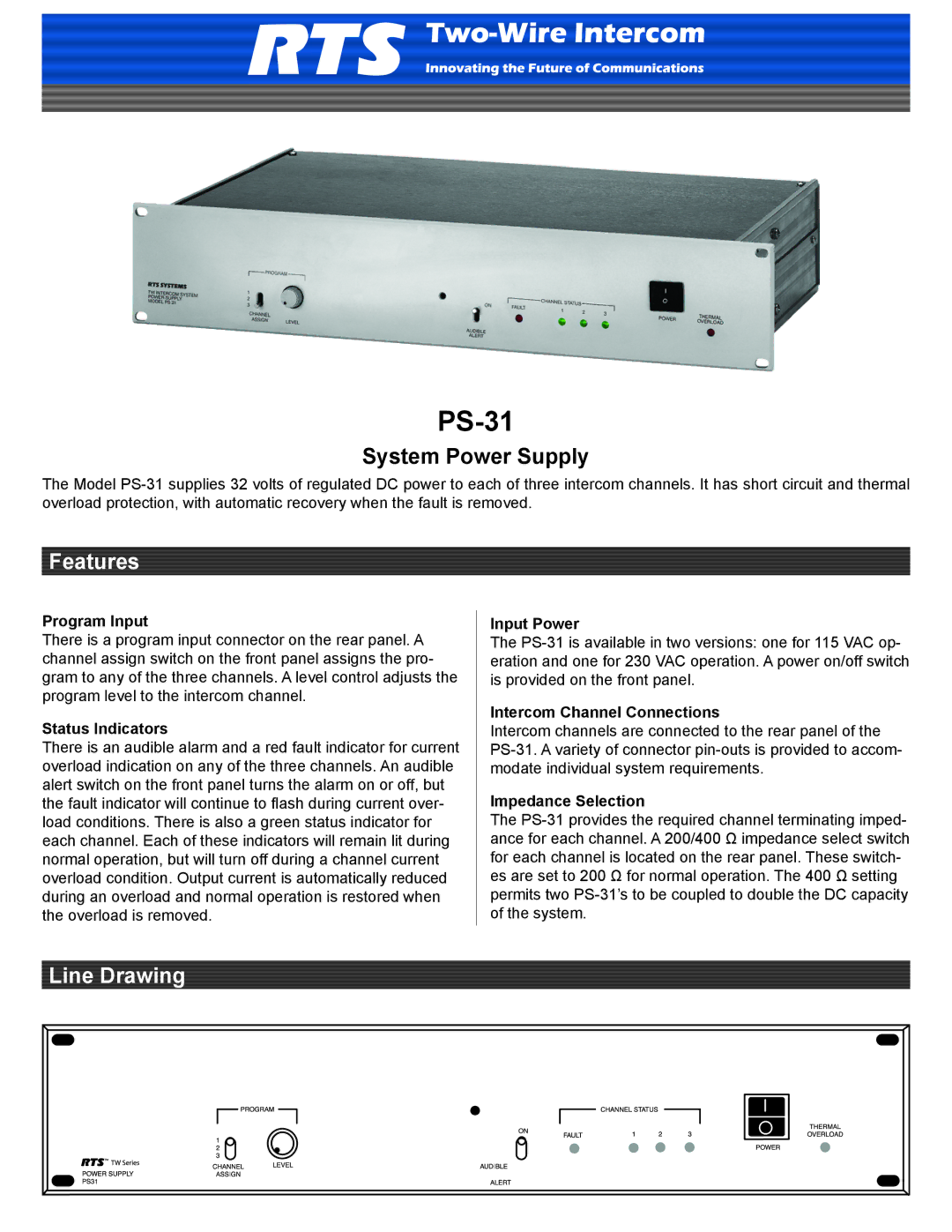
PS-31
System Power Supply
The Model
Features
Program Input
There is a program input connector on the rear panel. A channel assign switch on the front panel assigns the pro- gram to any of the three channels. A level control adjusts the program level to the intercom channel.
Status Indicators
There is an audible alarm and a red fault indicator for current overload indication on any of the three channels. An audible alert switch on the front panel turns the alarm on or off, but the fault indicator will continue to flash during current over- load conditions. There is also a green status indicator for each channel. Each of these indicators will remain lit during normal operation, but will turn off during a channel current overload condition. Output current is automatically reduced during an overload and normal operation is restored when the overload is removed.
Input Power
The
Intercom Channel Connections
Intercom channels are connected to the rear panel of the
Impedance Selection
The
Line Drawing