
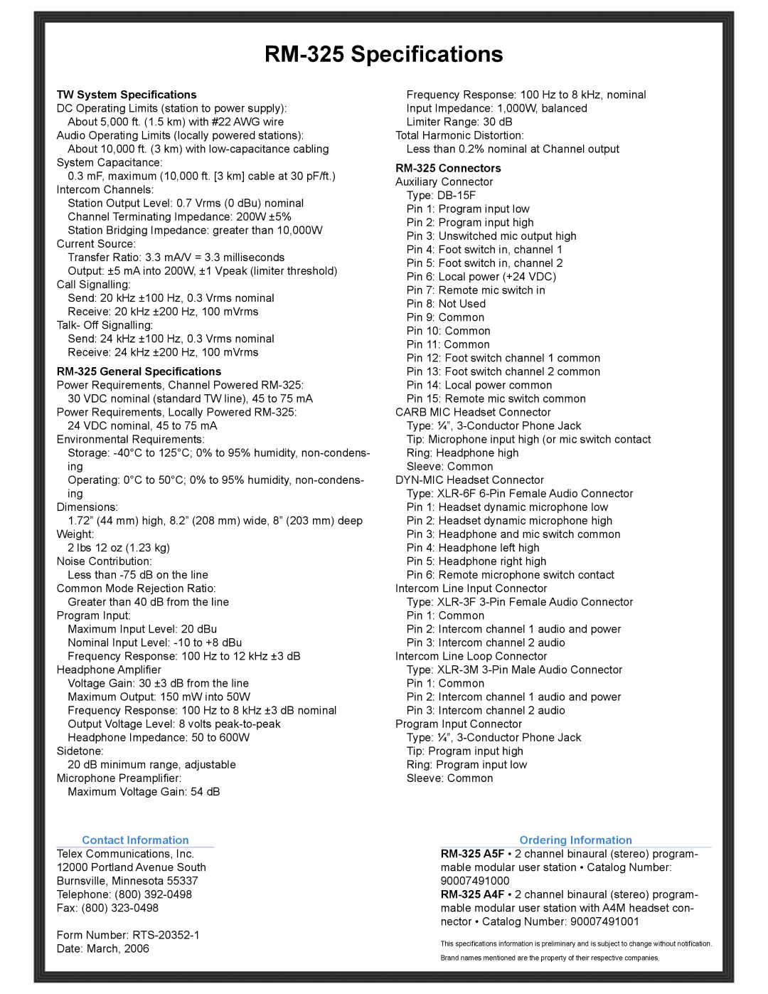
RM-325 specifications
The RTS RM-325 represents a significant advancement in the realm of tactical military radios, designed to meet the demanding needs of modern defense operations. This radio system is tailored specifically for use in challenging environments, providing robust and reliable communication capabilities essential for coordinating missions effectively.One of the standout features of the RTS RM-325 is its advanced frequency-hopping spread spectrum technology. This technology enables the radio to rapidly switch frequencies, making it resistant to jamming and eavesdropping attempts. Such capabilities are critical in combat scenarios where secure communication can determine the success or failure of a mission.
Another key characteristic of the RM-325 is its extensive range. With a communication range extending up to 50 kilometers in optimal conditions, the radio ensures that troops can stay connected over vast distances, maintaining operational cohesion even in dispersed formations. This long-range capability is complemented by its high-quality voice encoding, which ensures crystal-clear audio transmission, even in noisy battlefield environments.
The RTS RM-325 is also designed for interoperability with other military communication systems. It supports multiple communication protocols, allowing seamless integration with existing equipment. This flexibility is vital for joint operations where different branches of the military must work together using various communication platforms.
Moreover, the radio boasts a rugged design that can withstand extreme weather conditions, heavy shock, and vibrations. Its durability is crucial for field operations where equipment is exposed to the harsh realities of military engagements. The intuitive user interface further enhances usability, allowing operators to quickly navigate through functions and settings even in high-pressure situations.
In terms of power efficiency, the RM-325 is engineered to optimize battery usage, extending operational time without frequent recharges. This feature is particularly beneficial for long missions where access to power sources can be limited.
The RTS RM-325 also incorporates advanced encryption protocols, ensuring that sensitive information remains secure during transmission. This level of security is increasingly important in the information age, where cyber threats can compromise communication networks.
In summary, the RTS RM-325 is a cutting-edge tactical radio system equipped with advanced technologies that enhance communication capabilities in military operations. Its frequency-hopping technology, long-range communication, interoperability, rugged design, and security features make it an invaluable tool for today’s armed forces, ensuring that they can operate effectively and securely on the battlefield. As military operations continue to evolve, systems like the RTS RM-325 provide essential support, enhancing operational effectiveness and safety.