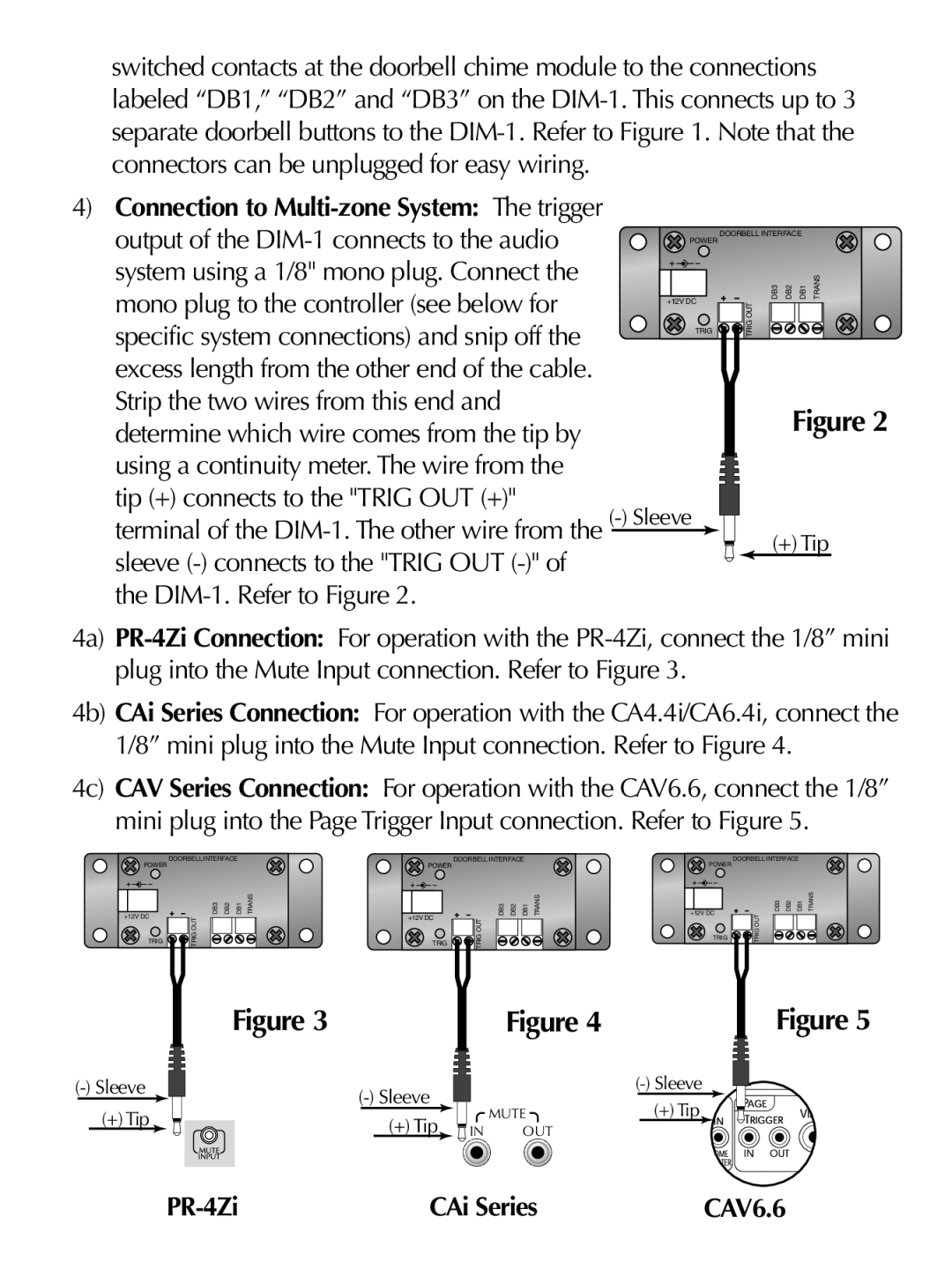
switched contacts at the doorbell chime module to the connections labeled “DB1,” “DB2” and “DB3” on the
4)Connection to Multi-zone System: The trigger
output of the | POWER | DOORBELL INTERFACE | |
|
| ||
|
|
| |
system using a 1/8" mono plug. Connect the |
|
| DB3 DB2 DB1 TRANS |
mono plug to the controller (see below for | +12V DC | OUT | |
| |||
specific system connections) and snip off the | TRIG | TRIG |
|
|
|
| |
excess length from the other end of the cable. |
|
|
|
Strip the two wires from this end and |
|
| Figure 2 |
determine which wire comes from the tip by |
|
| |
|
|
| |
using a continuity meter. The wire from the |
|
|
|
tip (+) connects to the "TRIG OUT (+)" |
|
|
|
terminal of the |
| (+) Tip | |
sleeve |
|
| |
|
|
| |
the |
|
|
|
4a)
4b) CAi Series Connection: For operation with the CA4.4i/CA6.4i, connect the 1/8” mini plug into the Mute Input connection. Refer to Figure 4.
4c) CAV Series Connection: For operation with the CAV6.6, connect the 1/8” mini plug into the Page Trigger Input connection. Refer to Figure 5.
DOORBELL INTERFACE
POWER |
|
|
|
|
+12V DC | DB3 | DB2 | DB1 | TRANS |
TRIG OUT |
|
|
| |
TRIG |
|
|
|
DOORBELL INTERFACE
POWER |
|
|
|
|
+12V DC | DB3 | DB2 | DB1 | TRANS |
TRIG OUT |
|
|
| |
TRIG |
|
|
|
DOORBELL INTERFACE
POWER |
|
|
|
|
+12V DC | DB3 | DB2 | DB1 | TRANS |
TRIG OUT |
|
|
| |
TRIG |
|
|
|
(+) Tip
Figure 3 |
| Figure 4 | Figure 5 |
|
| ||
| MUTE | (+) Tip | |
(+) Tip |
| ||
IN | OUT |
|
| CAi Series | CAV6.6 |
