4 Z O N E — 8 C H A N N E L A
POWER |
1 | 2 | 3 | 4 |
ZONE
FRONT PANEL
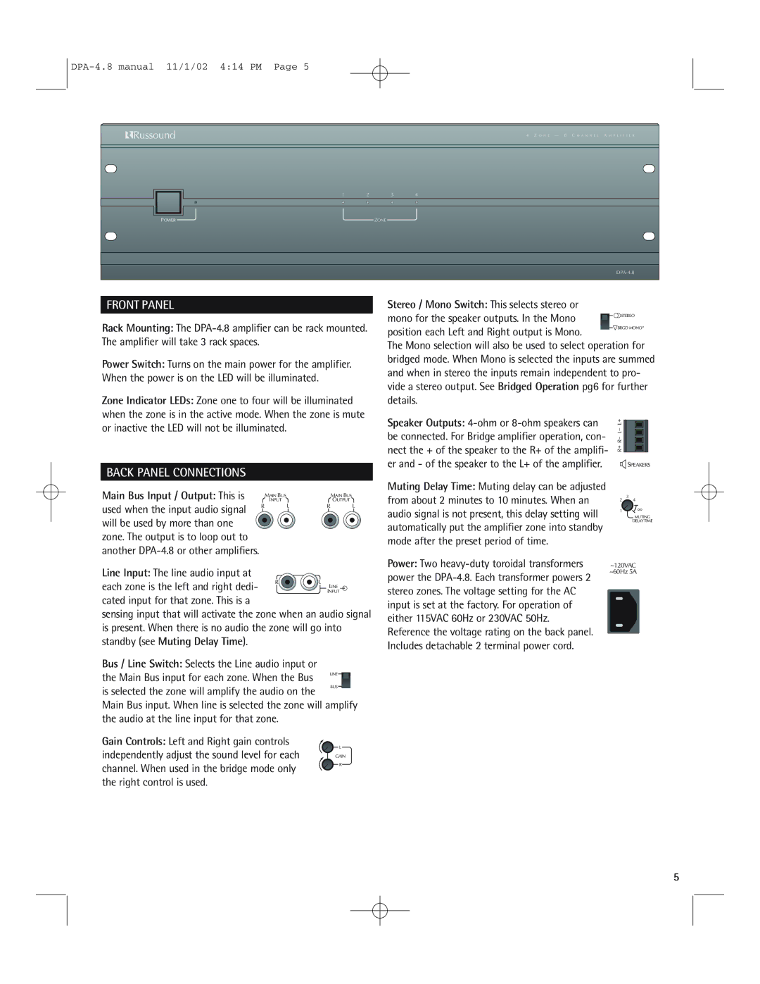
Rack Mounting: The
Power Switch: Turns on the main power for the amplifier. When the power is on the LED will be illuminated.
Zone Indicator LEDs: Zone one to four will be illuminated when the zone is in the active mode. When the zone is mute or inactive the LED will not be illuminated.
BACK PANEL CONNECTIONS
Main Bus Input / Output: This is |
| MAIN BUS |
| MAIN BUS |
| INPUT |
| OUTPUT | |
used when the input audio signal | R | L | R | L |
|
|
|
| |
will be used by more than one |
|
|
|
|
zone. The output is to loop out to |
|
|
|
|
another |
|
|
|
|
Speaker Outputs:
Muting Delay Time: Muting delay can be adjusted from about 2 minutes to 10 minutes. When an audio signal is not present, this delay setting will automatically put the amplifier zone into standby mode after the preset period of time.
![]() SPEAKERS
SPEAKERS
3
2 4
1 | ∞ |
|
MUTING
DELAY TIME
Line Input: The line audio input at | R | L | |
each zone is the left and right dedi- | |||
| LINE | ||
| INPUT |
cated input for that zone. This is a
sensing input that will activate the zone when an audio signal is present. When there is no audio the zone will go into standby (see Muting Delay Time).
Bus / Line Switch: Selects the Line audio input or
the Main Bus input for each zone. When the Bus LINE![]()
![]()
Power: Two | ~120VAC |
power the | ~60Hz 5A |
| |
stereo zones. The voltage setting for the AC |
|
input is set at the factory. For operation of |
|
either 115VAC 60Hz or 230VAC 50Hz. |
|
Reference the voltage rating on the back panel. |
|
Includes detachable 2 terminal power cord. |
|
is selected the zone will amplify the audio on the
BUS
Main Bus input. When line is selected the zone will amplify the audio at the line input for that zone.
Gain Controls: Left and Right gain controls
independently adjust the sound level for each | L |
GAIN | |
channel. When used in the bridge mode only | R |
| |
the right control is used. |
|
5
