Installation
1.Run CAT-5e cable up to 300 feet (90 m) between the VM1 and the video display locations in the zones.
Note: When running CAT-5e cables, avoid AC power wiring. If you have to run the cables parallel to electrical wiring, space the cable at least 12 inches (30 cm) from AC power lines.
2.Install single-gang UL/CSA-approved plastic wall boxes for the VMR1 receivers. Attach the boxes to the wall with appropriate fasteners.
3.In each zone, punch down the CAT-5e cable on the back of the VMR1 as indicated on the circuit board.
BR BR/W GRN G/W OR O/W BL BL/W
110 punch-down connection on rear of VMR1
4.Insert the VMR1 into the wall box and secure it with screws. Attach a wall plate.
5.Crimp RJ-45 connectors on the system end of the CAT-5e cables, following the T568A standard as shown.
RJ-45 Using T568A
Wiring Standard
6.Make sure the VM1 Video Matrix is turned off. Plug the RJ-45 connectors into the appropriate zone outputs on the VM1. (If using wall plates, punch down the CAT-5e per the T568A standard and use straight-through patch cables between the VM1 and the wall plates.)
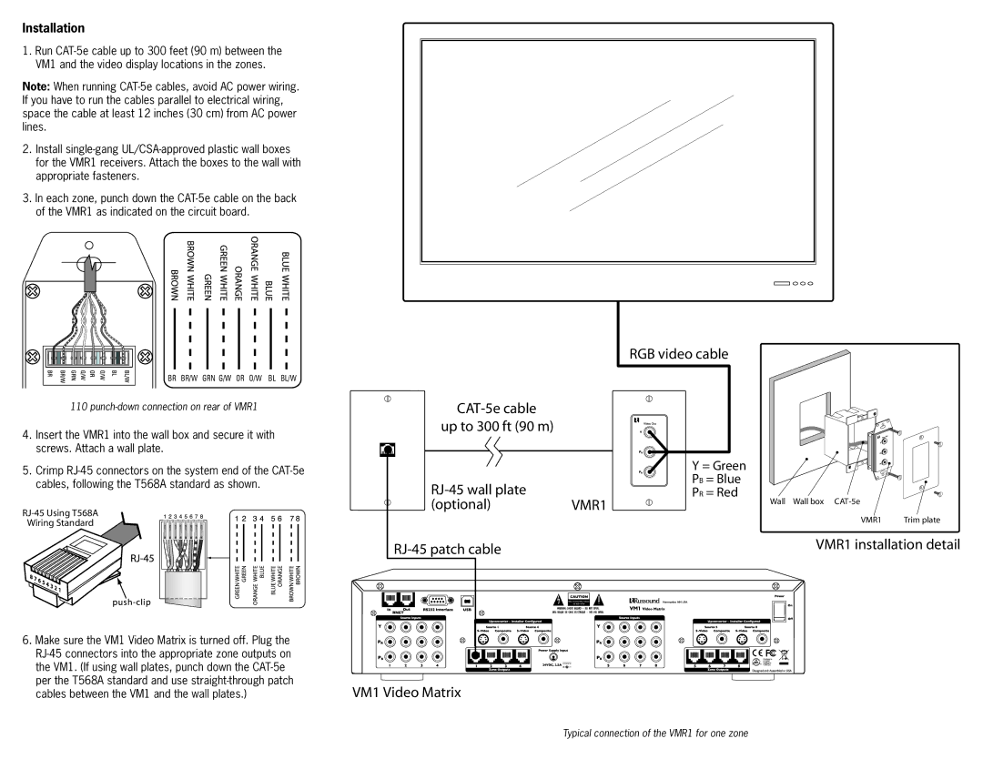
| | RGB video cable |
CAT-5e cable | | |
up to 300 ft (90 m) | | |
| | Y = Green |
RJ-45 wall plate | | PB = Blue |
| PR = Red |
(optional) | VMR1 | Wall Wall box CAT-5e |
|
| | VMR1 Trim plate |
RJ-45 patch cable | | VMR1 installation detail |
| |
VM1 Video Matrix
Typical connection of the VMR1 for one zone