Chassis KS3AP REV Model CS29A5HT8X/BWT
Color Television Receiver
Wire Cord
Safety Precautions
Plug Reversed
Samsung Electronics
Servicing Precautions
Precautions for Electrostatically Sensitive Devices ESDs
Tables of Abbreviations and Acronyms
Reference Information
Table of Acronyms
Board LOC. no Spec Description
IC Line Up
CRT
Board LOC. no Spec Description Remark Main
Focus
PIP
TCLS3101PD09AS
Spec Function Remark
TCPS3001PD09DS TCPS3001PD09ES
Function Remark
Specifications
Automatic Degaussing
General Alignment Instructions
High voltage Check
Screen Adjustment
Dynamic Focus Adjustment
Ibrm
White Balance Adjustment
E2PROM IC902 Replacement
Service Mode
Factory Adjustment
OSD
Memory Data
2B Screen Change I2C BUS Geometric Adjustment
~255
PAL
Soft Limit Slope B
2D Video 2 Adjust
Dolby
When PIP is 2-Tuner
Tuner
Scart + S
Slice Level
5 5 5
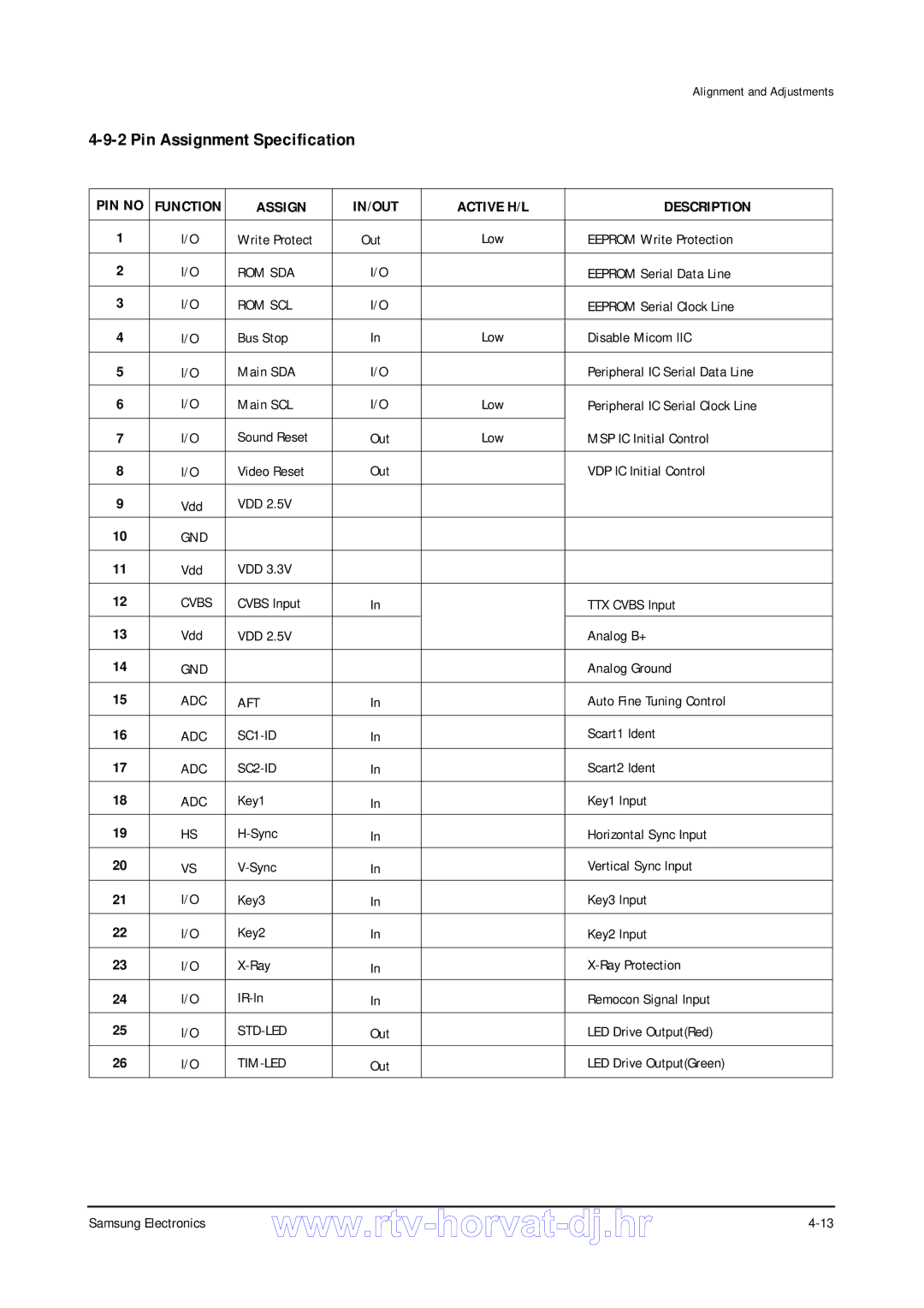
Assign Description
IN/OUT
Assign IN/OUT Active H/L Description
OFF
No Power
IC201S VDP
FBT
No Picture
No Sound
BADGE-BRANDAL,SS,SILVER,L65,R2000
INDICATOR-LED-,295A,-,ACRYL,-,CLR
WINDOW-REMOCON-,725A,-,PC,-,VIOLET
KNOB-CONTROL-,725A,-,ABS,HB,GRAY
CS29A5HT8X/BWT
TU01S
C841 AL1uF,20%,50V,WT,TP,5x11,5 DZ603
C840 AL10uF,20%,25V,WT,TP,5x11,5 DZ602
C901
DZ605
INDUCTOR-RADIAL10uH,10%,6x4mm R407
L904
L905
R409
ASSY-PCB SUB,AUTO AA95-00840A ,V
ICG01
DZF01
HOLDER-,P-CORD,PP,VO,BLK,KE-002
Assy Chassis PARTKS3A,295A
LDY01
DZY01
ASSY-PCB SUB,AUTO AA95-00681A ,V
DZY02
CF+AV
BOT
CZ21A8VW8X/ELS
Botz
ASSY-PCB Robot AA94-02037Z ,ER
C308 FILM,MPEF470nF,5%,63V,TP-,5mm C654
C307 AL100uF,20%,50V,GP,TP,8x11.5,5 C652
C402 AL470uF,20%,25V,GP,TP,10x16,5 C657
C404 AL470uF,20%,25V,GP,TP,10x16,5 C702
IC HYBRID-,DRGB001A,SIP,5P,-,TP
DIODE-RECTIFIERRU20A,600V,1.5A,-,TP
R223
R514
R520
R524
CLAMP-FBTABS,V0,BLK
Assy Cabinet Front
STOPPER-PCB501H,HIPS,NTR,HB
Back
AA59-00104A REMOCON-,TM59,DREAM,29,L/GRAY,-,EX,PA
CLAMP-D,COILNYLON 66,V0,-,-,21A8
Block Diagrams
Horvat-dj.hr
KEY3
KEY2 KEY1
STD
GND
RTV servis Horvat
Dj.hr
Horvat
TP26 TP33 TP35
Samsung Electronics 10-5
10-6 CRT, Side AV, Video Switch
Samsung Electronics 10-7
Double FOCUS, Control
