Rear |
5. Function |
3. Vertical Synchronization |
Phase Control Switch (left) |
1. Power Connection Terminal |
7. DC IRIS Level Regulator
6.Function
2.Power LED
8.Image Output Port
4.Vertical Synchronization Phase Control Switch (right)
Specifications
Model |
|
| |
Imaging Device |
| 1/3" Super HAD CCD, 410K(PAL:470K) pixels | |
Effective Pixels |
| NTSC : 768(H)x494(V) / PAL : 752(H)x582(V) | |
Scanning Method |
| 2:1 Interlace | |
Scanning Line |
| Horizontal | NTSC : 15.750Hz / PAL : 15.625Hz |
Frequency |
| Vertical | NTSC : 60Hz / PAL : 50Hz |
Synchronization Method | Internal / Line lock | ||
Horizontal Resolution | 540 TV Lines | ||
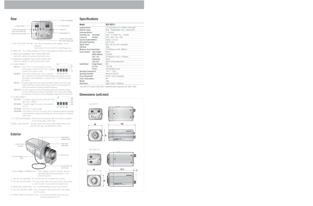
1.Power Connection Terminal : This is the terminal where a power (adaptor) cable is connected.
Connect either AC24V or DC12V for power Requirment.
2.Power LED : The LED light is turned on if power is being supplied normally to the camera.
3.Vertical Synchronization Phase Control Switch (left)
:Used when adjusting the vertical synchronization phase.
4.Vertical Synchronization Phase Control Switch (right)
:Used when adjusting the vertical synchronization phase.
5. Function Switch-1
· SW1(L/L) : If set to ‘OFF,’ the camera operates in internal synchronization mode and if set to ‘ON,’ it operates
in power synchronization mode. · SW2(ELC) : If this switch, selected when using a manual iris
lens, is switched on, the electronic shutter speed is automatically controlled according to screen brightness, in a range of 1/60~1/120,000 exposures per second.
·SW3(FL) : This switch triggers the
·SW4(LSS): This switch triggers the enhanced sensitivity mode, which eliminates image noise by consistently accumulating image fields in the memory when images are captured in a dark place, and by increasing the brightness and contrast ratio.
6. Function |
|
|
|
|
|
|
|
|
|
|
|
|
|
|
| ON | 1. AGC | ||||||||||||
· SW1(AGC) : This switch is used to turn the camera AGC (Auto |
| |||||||||||||
|
|
|
|
|
|
|
|
|
|
|
|
| 2. DNR | |
|
|
|
|
|
|
|
|
|
|
|
|
| ||
Gain Control) ON/OFF. |
|
|
|
|
|
|
|
|
|
|
|
|
| 3. D&N |
|
|
|
|
|
|
|
|
|
|
|
|
| ||
· SW2(DNR) : This switch triggers the random noise reduction |
|
|
|
|
|
|
|
|
|
|
|
|
| 4. AWB |
function. |
|
|
|
|
|
|
|
|
|
|
|
|
|
|
SW1 SW2 SW3 SW4 |
| |||||||||||||
|
| |||||||||||||
·SW3(D&N) : This refers to the Day & Night.
·SW4(AWB) : If this switch is set to ON, the screen color is automatically adjusted according to the temperature change of the lighting color due to changes in the external environment.
7.DC IRIS Level Regulator : When the ALC lens selection switch is set to DC, it regulates the iris level by using a control lever.
8.Video Output Terminal : The video signal of the camera can be outputted through this terminal to the video input terminal of a monitor.
Signal Output |
| VBS |
S/N Ratio |
| 50dB |
Minimum Scene Illumination | 0.0009(Sens up 128X,15IRE)Lux | |
Control Switch | Day & Night | Off/On |
| White Balance | ATW/AWC |
| ALC / ELC | ALC(Video/DC) / ELC(~1/120Ksec) |
| Flickerless | Off/On |
| Line lock | Off/On |
Input/Output | Image Output | BNC |
| AI Lens | |
| Power | Terminal Block |
Operating Temperature | ||
Operating Humidity | Maximum 90% RH | |
Power Requirment | AC24V / DC12V compatible | |
Power Consumption | 3W | |
Weight |
| 440g |
Dimensions |
| 68(W) x 55(H) x 138(D)mm |
*
Dimensions (unit:mm)
Exterior
3.Auto Iris Lens Connector
5.ALC Lens Selection Switch
1. Mount Adaptor
Installation Holes
4. Flange Back
Control Ring
2. Auto Iris Lens
6. Control Cable for the Auto Iris Lens
|
1.Mount Adaptor Installation Holes : When installing a camera to a bracket, these are used when fastening the mount adaptor to the bracket with screws.
2.Auto Iris Lens (optional) : This is the lens that can be installed onto a camera.
3.Auto Iris Lens Connector : The power, control signal, video signal and DC signal needed to control the lens iris are provided to the auto iris lens.
4.Flange Back Control Ring : This is used for controlling the back focus of camera.
5.ALC Lens Selection Switch : This is the switch for selecting the type of lens installed onto the camera.
6.Control Cable for the Auto Iris Lens : This transmits the control signal sent by the camera to control the lens iris.
