Manuals
/
Sanyo
/
Computer Equipment
/
Computer Monitor
Sanyo
42LM5RTC Diagnostics And Frequently Asked Questions, Testing the Hardware with ‘Graph’
Models:
42LM4WPTC
42LM4RTC
42LM5RTC
1
15
19
19
Download
19 pages
27.74 Kb
12
13
14
15
16
17
18
19
Install
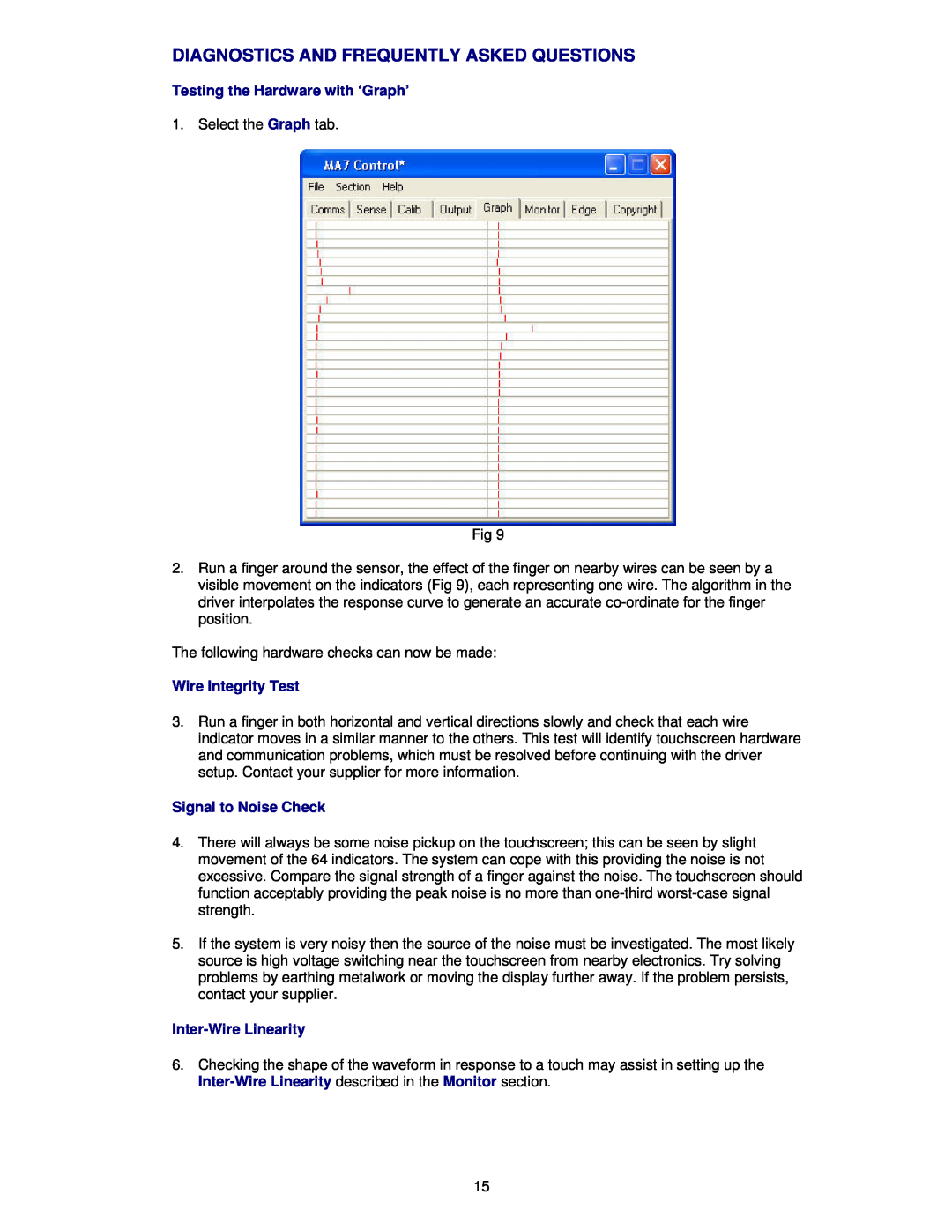
Signal to Noise Check
Fault Finding Guide
Automatic Setup
You must now save the settings
Using Edge Enhancement
Page 15
Image 15
Page 14
Page 16
Page 15
Image 15
Page 14
Page 16
Contents
Interactive Touchscreen User Guide
Interactive Touchscreen User Guide
42LM4WPTC 42LM5WPTC 42LM4RTC 42LM5RTC
For serial Interface
Page
TABLE OF CONTENTS
SHIPPING DAMAGE/UNPACKING
CARE AND CLEANING OF THE TOUCHSCREEN
ABOUT THIS MANUAL
CONTACT INFORMATION
COMPATIBILITY
INTRODUCTION
INSTALLATION
LOADING THE TOUCH DRIVER SOFTWARE ONTO PC
Do not plug the touchscreen interface cable into your computer
STARTING THE DRIVER CONTROL PROGRAM
CONFIGURING THE COMMUNICATIONS PORT
EXPLANATION OF THE STATUS SECTION
Reasons why the driver does not see the touchscreen are usually
Page
ADJUSTING THE TOUCH SENSITIVITY LEVEL
Automatic Setup
Manual Sensitivity Setup
Page
CALIBRATION
To enable the touch function on the screen, tick the Enable check box
SETTING THE TOUCH OUTPUT TO SUIT THE APPLICATION PROGRAM
1. Fig 8 Click on file 2. Click on save to save the current settings
You must now save the settings
Signal to Noise Check
DIAGNOSTICS AND FREQUENTLY ASKED QUESTIONS
Testing the Hardware with ‘Graph’
Wire Integrity Test
MONITOR MODE
DELAYED STARTING OF THE DRIVER OUTPUT
USING EDGE ENHANCEMENT
DRIVER DOES NOT SEE THE TOUCHSCREEN
FAULT FINDING GUIDE
PROBLEMS WITH WINDOWS AUTOMATICALLY RUNNING THE DRIVER FROM START- UP
SLOW TOUCH SCREEN RESPONSE WHEN USING POWER HUNGRY APPLICATIONS
@echo off start /high c\program files\TouchScreen\MA7Driver.exe
CHECK OR CHANGE THE VIRTUAL MEMORY SETTINGS
To set the priority settings permanently when the system restarts
DRIVER PRIORITY CHANGE
Top
Page
Image
Contents