
PLC-XL51 specifications
The Sanyo PLC-XL51 is a powerful and versatile portable projector, lauded for its impressive features and advanced technology, making it a preferred choice for both professional presentations and home entertainment.One of the standout characteristics of the PLC-XL51 is its light output. With a brightness rating of 2,000 ANSI lumens, it delivers clear and vivid images even in moderately lit environments. This feature ensures that presentations maintain their impact without the need for complete dimming of surroundings, enhancing the viewing experience for audiences.
The projector utilizes LCD technology, renowned for its ability to produce bright colors and sharp details. The three-panel design of the PLC-XL51 ensures accurate color reproduction, achieving stunning visuals that captivate viewers. This makes the projector ideal for showcasing multimedia presentations, graphs, and images during meetings or seminars.
Another major feature of the Sanyo PLC-XL51 is its resolution. It offers XGA resolution (1024x768), providing a crisp picture quality that is suitable for various types of content, from text-heavy slides to high-resolution videos. The projector's native resolution is particularly beneficial for educational and business settings, where clarity and precision are paramount.
Portability is another defining characteristic of the PLC-XL51. Weighing in at just 2.7 kg (approximately 6 lbs), it boasts a compact design that enables easy transportation. The projector is equipped with a carrying case and features a quick setup function, allowing users to begin presentations with minimal hassle.
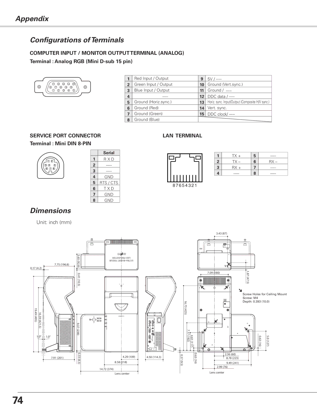
Connectivity options are plentiful, featuring inputs such as VGA, composite video, and audio, which ensure compatibility with a wide range of devices. This versatility facilitates seamless integration with laptops, DVD players, and even gaming consoles for versatile usage.
The Sanyo PLC-XL51 also incorporates a user-friendly interface and intuitive remote control, making it easy to navigate settings. Features such as keystone correction help in adjusting the image for optimal display, while digital zoom and pan functionalities enhance control over presentation visuals.
Overall, the Sanyo PLC-XL51 combines impressive brightness, excellent image quality, and portability, making it an ideal choice for professionals and educators alike. Its array of features and ease of use ensure that it remains a formidable contender in the projection market, appealing to users seeking reliability and performance in their visual presentations.