
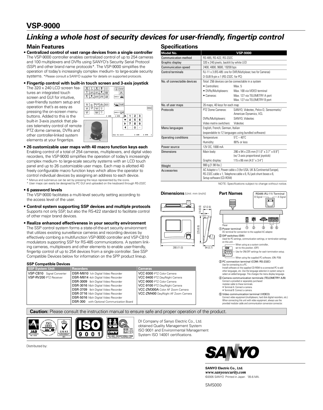
VSP-9000 specifications
The Sanyo VSP-9000 is a highly advanced video wall display processor designed to provide exceptional image quality and flexible configuration for various professional applications. This product stands out for its ability to manage multiple video sources and deliver seamless content across large display surfaces, making it an ideal choice for control rooms, broadcast studios, and corporate environments.One of the main features of the Sanyo VSP-9000 is its ability to support high-definition resolutions, including 4K, ensuring that the content displayed is sharp, detailed, and visually engaging. This processor is equipped with powerful scaling technology, allowing it to take input from numerous sources, including laptops, cameras, and streaming devices, and output that content to video walls with varying resolutions and configurations.
The VSP-9000 utilizes advanced digital signal processing algorithms that enhance image quality by providing features like noise reduction, contrast enhancement, and color calibration. This ensures that the images are not only vibrant but also consistent across all screens, addressing the challenges posed by misalignment or different screen technologies used in a video wall setup.
Another key characteristic of the Sanyo VSP-9000 is its modular design. Users can customize their video wall setups by selecting various input and output modules, which facilitates connectivity with a wide range of video formats and signal types. This modularity allows for easy upgrades and scalability, accommodating the evolving needs of users as technology advances.
The processor also supports real-time video compositing, enabling users to display multiple channels of content on a single screen or distribute a single video source across multiple screens seamlessly. Users can easily manage the layout and content through an intuitive user interface, which simplifies the operation and enhances productivity.
Networking capabilities are integral to the VSP-9000, allowing for remote control and monitoring via standard network protocols. This feature is particularly useful for large installations where access to the processor may be limited.
In summary, the Sanyo VSP-9000 represents a sophisticated solution for anyone looking to create dynamic and visually striking video wall presentations. Its high-definition output, advanced processing technologies, modular design, and robust connectivity options make it well-suited for diverse applications in various professional environments.