CT4xx Series Quick Guide | Pg 8 |
ON LINE KEY If the ONLINE LED is illuminated, pressing this switch will place | |
the printer in the OFFLINE mode. If this switch is pressed during | |
printing, the printing process is suspended. To resume printing, | |
CT4xx Series Quick Guide | Pg 5 |
Note: CT Series ribbons are wound face (ink side) out. Make sure the dull (ink) side of the ribbon will be in contact with the paper and the supply core is on the rear spindle.
| press this switch again. |
FEED Key | Feeds one label when pressed in the OFFLINE mode. If this switch |
| is held in the depressed position while power is applied, a printer |
| status label will be printed. |
POWER | A |
| “0” position is pressed, power is removed from the printer. When |
| the “1” position is pressed, power is applied to the printer. |
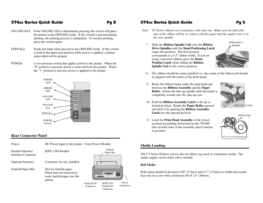
7.Slide the Ribbon Spindle Unit over the Ribbon Drive Spindles until the Head Positioning Latch snaps into position. The first position corresponds to a 4.3” ribbon width. If you are using a narrower ribbon, press the Head Position Latch while sliding the Ribbon Spindle Unit to the correct position.
Ribbon Drive
Spindles
| POWER |
| |
| LED |
| |
| ERROR |
| |
| LED |
| |
| ON LINE |
| |
| LED |
| |
| ON LINE |
| |
| Key |
| |
| FEED Key |
| |
| POWER |
| |
| Switch |
| |
Rear Connector Panel |
| ||
Power | DC Power input to the printer. From Power Module | ||
Parallel Interface | IEEE 1284 Parallel | Fanfold | |
Paper Slot | |||
Interface Connector |
| ||
|
| ||
Optional Interface | Connector for any installed |
| |
Fanfold Paper Slot | Slot for fanfold paper. |
| |
| Panel must be removed to |
| |
route fanfold paper into the printer
8.The ribbon should be centre justified (i.e. the centre of the ribbon roll should be aligned with the centre of the print head).
9.Route the ribbon leader under the print head and between the Ribbon Assembly and the Paper Roller. Rotate the
10.Push the Ribbon Assembly Latch to the up or
locked position. Rotate the Paper Roller upward | Label Ass’y Latch | |
and latch it by pushing the Ribbon Assembly |
| |
Latch into the upward position. | Ribbon Path | |
11. Latch the Print Head Assembly in the closed | ||
| ||
position by pushing downward on the “PUSH” |
| |
tabs on both sides of the assembly until it latches |
| |
in position. |
|
Media Loading
The CT Series Printers can use
Roll Media
Roll media should be between 0.90” (23mm) and 4.5” (115mm) in width and wound
Optional I/F | IEEE1284 | Power |
Connector | Parallel I/F | Connector |
| Connector |
|