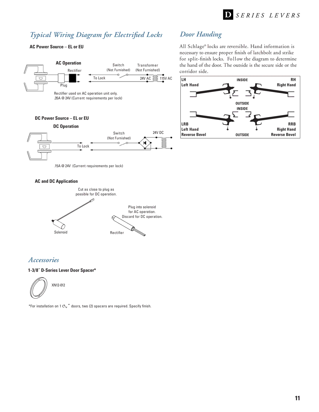
D-Series specifications
The Schlage D-Series represents a pinnacle in commercial door hardware, merging sophisticated technology with robust performance. Designed for high-traffic environments, the D-Series guarantees security without compromising accessibility.One of the standout features of the Schlage D-Series is its pivotal locking mechanism, which incorporates the patented Schlage Everest keyway. This provides enhanced protection against unauthorized duplication, ensuring that only authorized users can gain access. Furthermore, the D-Series offers an extensive range of cylinder options, accommodating various security levels dictated by the specific needs of a facility.
Durability is a cornerstone of the D-Series design. Crafted from heavy-duty materials, each component is engineered to withstand rigorous use typical in commercial settings. The finish is not only aesthetically pleasing but also resistant to corrosion and wear, ensuring longevity and a consistent appearance over time.
The Schlage D-Series also features a modular design that simplifies installation and maintenance. This system allows for easy swapping of parts without the need for specialized tools, reducing downtime and labor costs significantly. Whether it’s a simple cylinder change or an upgrade to electronic access control, the D-Series can adapt to meet evolving security requirements.
Speaking of technology, the D-Series offers options that integrate seamlessly with electronic access control systems. This adaptability ensures that facilities can implement advanced security measures while maintaining the classic feel of traditional hardware. Schlage’s electronic locks within the D-Series can also be managed remotely, enabling real-time tracking of access and simplifying audits.
Another notable characteristic is the multi-point locking capabilities, which provide an added layer of security ideal for larger entryways or facilities requiring enhanced protection.
In terms of aesthetics, the Schlage D-Series is available in numerous finishes and configurations, allowing users to create a cohesive look with other hardware across their properties.
In summary, the Schlage D-Series exemplifies a blend of security, durability, and modern technology. With its variety of features tailored for commercial applications, it stands out as a trustworthy choice for businesses aiming to bolster their security posture while ensuring efficient access control. Whether for a retail space, office building, or educational institution, the D-Series is designed to meet the demands of modern security challenges.

