L S E R I E S
Electrified Locks
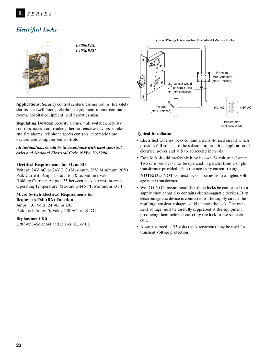
Typical Wiring Diagram for Electrified
L9080PEL
L9080PEU
Frame to
Door Connector
(Not Furnished)
Varistor would
go here if used ![]() (Not Furnished)
(Not Furnished)
Applications: Security control centers, cashier rooms, fire safety alarms, stairwell doors, telephone equipment rooms, computer rooms, hospital equipment, and narcotics areas.
Regulating Devices: Security alarms, wall switches, security consoles, access card readers,
All installations should be in accordance with local electrical codes and National Electrical Code, NFPA
Electrical Requirements for EL or EU
Voltage: 24V AC or 24V DC (Maximum 29V, Minimum 20V)
Peak Current: Amps 1.3 at 5 to 10 second intervals
Holding Current: Amps .135 between peak current intervals.
Operating Temperature: Maximum +151°F, Minimum
Micro Switch Electrical Requirements for
Request to Exit (RX) Function
Amps, 1.0; Volts, 24 AC or DC
Peak load: Amps, 5; Volts, 250 AC or 28 DC
Replacement Kit
Switch | 24V AC | 115V AC |
(Not Furnished)
Transformer
(Not Furnished)
Typical Installation
•Electrified
•Each lock should preferably have its own 24 volt transformer. Two or more locks may be operated in parallel from a single transformer provided it has the necessary current rating.
NOTE: DO NOT connect locks in series from a higher volt- age rated transformer.
•We DO NOT recommend that these locks be connected to a supply circuit that also contains electromagnetic devices. If an electromagnetic device is connected to the supply circuit the resulting transient voltages could damage the lock. The tran- sient voltage must be carefully suppressed at the equipment producing them before connecting the lock to the same cir- cuit.
•A varistor rated at 35 volts (peak recurrent) may be used for transient voltage protection.
20