5.Set the COM properties as follows: Bits per second = 19200, Data bits = 8, Parity = None, Stop bits = 1, and Flow control = None.
6.Click OK.
7.Start the ETG Setup Utility:
a.Cycle power or press the reset button on the ETG.
b.While the green Power/Status LED blinks rapidly, press Enter on the computer keyboard to access the setup utility. See Table 2 for a description of the setup options.
NOTE: The Power/Status LED stops blinking after 5 seconds.
Table 2: ETG Setup Utility Options
Option | Description | Setting | |
1 | Used to select the language for the current | English, French, Spanish, German | |
HyperTerminal session. | Default: English | ||
| |||
|
|
| |
2 | Used to select the format for data sent over an | Ethernet II, 802.3 SNAP | |
Ethernet connection. | Default: Ethernet II | ||
| |||
|
|
| |
| Used to enter the static IP address of the ETG. |
| |
3 | NOTE: If you enter an IP address that is already | 0.0.0.0 to 255.255.255.255 | |
in use, you will be prompted to select a different | Default: 169.254.0.10 | ||
| |||
| IP address. |
| |
|
|
| |
4 | Used to enter the subnet mask of your network. | 0.0.0.0 to 255.255.255.255 | |
Default: 255.255.0.0 | |||
|
| ||
|
|
| |
| Used to enter the default gateway (router) IP | 0.0.0.0 to 255.255.255.255 | |
5 | address used for wide area network (WAN) | ||
Default: 0.0.0.0 | |||
| communications. | ||
|
| ||
|
|
| |
|
| • 10T/100Tx Auto |
Serial Configuration
1.Start Internet Explorer.
2.In the Address text box, type the IP address assigned to your ETG, then press Enter.
3.Type Administrator for your user name, type Gateway for your password, then click OK.
4.Click Serial Port or Device List as appropriate and proceed to the sections below.
Serial Port
1.Click Serial Port.
2.Select the mode, physical interface, transmission mode, baud rate, and parity for the serial COM port. NOTE: Attached serial devices must have the same baud rate, parity, and wiring mode settings. If you are using RS485, set the mode according to whether your daisy chain is
Parameter | Options | Default Setting |
Mode | Master, Slave | Master |
|
|
|
Physical Interface | RS485 | RS485 |
|
|
|
Transmission Mode | Modbus RTU, Modbus ASCII | Modbus RTU |
|
|
|
Baud Rate | 2400, 4800, 9600, 19200, 38400, 56000➀, 57600➀ | 19200 |
Parity | Even, Odd, None | Even |
|
|
|
➀ RS232/Modbus ASCII only.
3.If Mode is set to Slave, enter a unique IP address for each remotely connected device. See the User’s Guide
4.Click Apply to save changes.
Device List
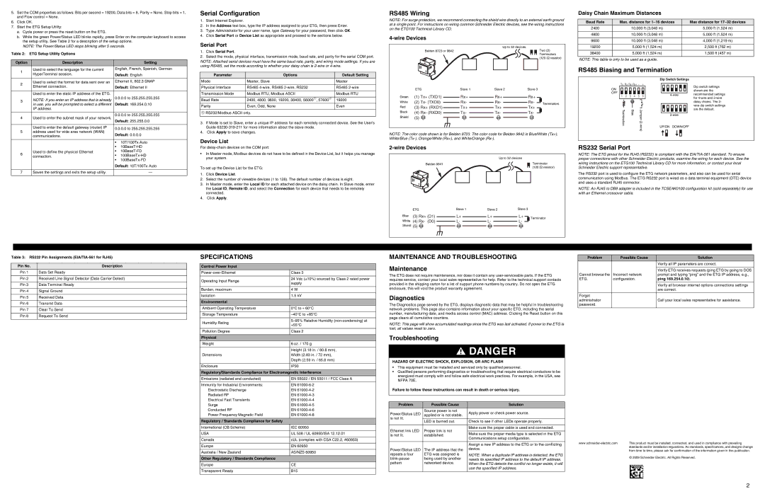
RS485 Wiring |
|
|
|
|
|
|
|
|
|
|
| Daisy Chain Maximum Distances |
| |
NOTE: For surge protection, we recommend connecting the shield wire directly to an external earth ground |
|
|
|
| ||||||||||
| Baud Rate | Max. distance for | Max distance for | |||||||||||
at a single point. For instructions on wiring common Schneider Electric devices, see the wiring instructions |
| |||||||||||||
| 2400 | 10,000 ft (3,048 m) | 5,000 ft (1,524 m) | |||||||||||
on the ETG100 Technical Library CD. |
|
|
|
|
|
|
|
|
|
|
| |||
|
|
|
|
|
|
|
|
|
|
|
| 4800 | 10,000 ft (3,048 m) | 5,000 ft (1,524 m) |
|
|
|
|
|
|
|
|
|
|
|
|
|
| |
|
|
|
|
|
|
|
|
|
|
| 9600 | 10,000 ft (3,048 m) | 4,000 ft (1,219 m) | |
|
|
|
|
|
|
|
|
|
|
|
| |||
|
|
|
|
|
|
|
|
|
|
|
|
|
|
|
|
|
| Up to 32 devices. |
| 19200 | 5,000 ft (1,524 m) | 2,500 ft (762 m) | |||||||
Belden 8723 or 9842 |
|
|
|
|
|
|
|
|
| Two (2) |
|
|
|
|
|
|
|
|
|
|
|
|
|
| Terminators |
| 38400 | 5,000 ft (1,524 m) | 1,500 ft (457 m) |
|
|
|
|
|
|
|
|
|
| (120 Ω resistor) |
|
|
|
|
|
|
|
|
|
|
|
|
|
|
| NOTE: This table is only to be used as a guide. |
| ||
|
|
|
|
|
|
|
|
|
|
|
|
| ||
|
|
|
|
| RS485 Biasing and Termination |
| |||||||
|
|
|
|
|
|
|
|
|
| Dip Switch Settings |
| ||
|
|
|
|
| Tx Rx Rx- Rx+ – | + |
| Dip switch settings | |||||
| ETG | Slave 1 | Slave 2 | Slave 3 | ON |
|
|
|
|
|
| ||
|
|
|
|
|
|
| shown are the | ||||||
|
|
|
|
| OFF |
|
|
|
|
|
| ||
|
|
|
|
|
|
|
|
|
| recommended settings | |||
Green | (1) Tx+ (TXD1) | Rx+ | Rx+ | Rx+ | 1 | 2 | 3 | 4 | 5 | 6 | |||
| for | ||||||||||||
|
|
|
|
|
|
| |||||||
White | (2) Tx- (TXD0) | Rx- | Rx- | Rx- | Terminators |
|
|
|
|
|
| daisy chains. The 2- | |
Red | (3) Rx+ (RXD1) | Tx+ | Tx+ | Tx+ |
|
|
|
|
|
| wire dip switch settings | ||
|
|
|
|
|
|
| |||||||
| Termination |
| Bias |
|
| are the default. | |||||||
Black | (4) Rx- (RXD0) | Tx- | Tx- | Tx- |
|
|
|
| |||||
|
|
|
| ||||||||||
Shield | (5) |
|
|
|
|
|
|
|
|
|
| ||
|
|
|
|
|
|
|
|
|
|
| |||
|
|
|
|
|
|
|
|
|
| UP/ON | DOWN/OFF |
| |
NOTE: The color code shown is for Belden 8723. The color code for Belden 9842 is Blue/White (Tx+),
White/Blue (Tx-), Orange/White (Rx+), and White/Orange (Rx-).
|
| • | ||
6 | Used to define the physical Ethernet | • | ||
connection. | • | |||
| ||||
|
| • | ||
|
| Default: 10T/100Tx Auto | ||
|
|
|
| |
7 | Saves the settings and exits the setup utility. |
| — | |
For
•In Master mode, Modbus devices do not have to be defined in the Device List, but it helps you manage your system.
To set up the Device List for the ETG:
1.Click Device List.
2.Select the number of viewable devices (1 to 128). The default number of devices is eight.
3.In Master mode, enter the Local ID for each attached device on the daisy chain. In Slave mode, enter the Local ID, Remote ID, and select the Connection for each device that needs to be remotely connected.
4.Click Apply.
2-wire Devices
|
|
| Up to 32 devices |
| |||
Belden 9841 |
|
|
|
|
| Terminator | |
|
|
|
|
| |||
|
|
|
|
|
| (120 | Ω resistor) |
|
|
|
|
|
|
|
|
|
|
|
|
|
|
|
|
| ETG |
| Slave 1 | Slave 2 | Slave 3 |
| |||
Blue | (3) Rx+ (D1) |
| L+ |
| L+ |
| L+ |
| Terminator |
White | (4) Rx- (D0) |
| L- |
| L- |
| L- |
| |
|
|
|
|
| |||||
|
|
|
|
| |||||
Shield (5) ![]()
RS232 Serial Port
NOTE: The ETG pinout for the RJ45 (RS232) is compliant with the
The RS232 port is used to configure the ETG network parameters, and also can be used for serial communication using Modbus. The ETG RS232 port is wired as a data terminal equipment (DTE) device and uses a standard RJ45 connector.
NOTE: An RJ45 to DB9 adapter is included in the TCSEAK0100 configuration kit (sold separately) for use with an Ethernet crossover cable.
Table 3: RS232 Pin Assignments
Pin No. | Description |
Pin 1 | Data Set Ready |
|
|
Pin 2 | Received Line Signal Detector (Data Carrier Detect) |
|
|
Pin 3 | Data Terminal Ready |
|
|
Pin 4 | Signal Ground |
|
|
Pin 5 | Received Data |
|
|
Pin 6 | Transmit Data |
|
|
Pin 7 | Clear To Send |
|
|
Pin 8 | Request To Send |
|
|
SPECIFICATIONS
Control Power Input
Class 3 | ||
|
| |
Operating Input Range | 24 Vdc (±10%) sourced by Class 2 rated power | |
supply | ||
| ||
|
| |
Burden, maximum | 4 W | |
|
| |
Isolation | 1.5 kV | |
|
| |
Environmental |
| |
Ambient Operating Temperature | 0°C to + 60°C | |
|
| |
Storage Temperature | ||
|
| |
Humidity Rating | ||
+55°C | ||
| ||
|
| |
Pollution Degree | Class 2 | |
|
| |
Physical |
| |
Weight | 6 oz. / 170 g | |
|
| |
| Height (3.18 in. / 80.8 mm), | |
Dimensions | Width (2.83 in. / 72 mm), | |
| Depth (2.59 in. / 65.8 mm) | |
|
| |
Enclosure | IP30 | |
|
| |
Regulatory/Standards Compliance for Electromagnetic Interference | ||
Emissions (radiated and conducted) | EN 55022 / EN 55011 / FCC Class A | |
|
| |
Immunity for Industrial Environments: | EN | |
Electrostatic Discharge | EN | |
Radiated RF | EN | |
Electrical Fast Transients | EN | |
Surge | EN | |
Conducted RF | EN | |
Power Frequency Magnetic Field | EN | |
|
| |
Regulatory / Standards Compliance for Safety |
| |
International (CB Scheme) | IEC 60950 | |
|
| |
USA | UL 508 / UL 60950/ISA 12.12.01 | |
|
| |
Canada | cUL (complies with CSA C22.2, #60950) | |
|
| |
Europe | EN 60950 | |
|
| |
Australia / New Zealand | AS/NZS 60950 | |
|
| |
Other Regulatory / Standards Compliance |
| |
Europe | CE | |
|
| |
Transparent Ready | B15 | |
|
| |
MAINTENANCE AND TROUBLESHOOTING
Maintenance
The ETG does not require maintenance, nor does it contain any
Diagnostics
The Diagnostics page served by the ETG, displays diagnostic data that may be helpful in troubleshooting network problems. This page also contains information about your specific ETG, including the serial number, manufacturing date, and media access control (MAC) address. Clicking the Reset button on this page clears all cumulative counters.
NOTE: This page will show accumulated readings since the ETG was last activated. If power to the ETG is lost, all values reset to zero.
Troubleshooting
![]() DANGER
DANGER
HAZARD OF ELECTRIC SHOCK, EXPLOSION, OR ARC FLASH
•This equipment must be installed and serviced only by qualified personnel.
•Qualified persons performing diagnostics or troubleshooting that require electrical conductors to be energized must comply with and follow safe electrical work practices. For example, in the USA, see NFPA 70E.
Failure to follow these instructions can result in death or serious injury.
Problem | Possible Cause | Solution | |
Power/Status LED | Source power is not | Apply power or check power source. | |
applied or is not stable. | |||
| |||
is not lit. |
|
| |
LED is burned out. | Check to see if other LEDs operate properly. | ||
| |||
|
|
| |
Ethernet link LED | Proper link is not | Make sure the proper cable is used and connected. | |
| |||
Make sure the proper media type is selected in the ETG | |||
is not lit. | established. | ||
Communications setup configuration. | |||
|
| ||
|
|
| |
|
| Assign a new IP address to the ETG or to the conflicting | |
Power/Status LED | The IP address that the | device. | |
repeats a four | ETG was assigned is | NOTE: When a duplicate IP address is detected, the ETG | |
being used by another | resets its specified IP address to the default IP address. | ||
pattern | networked device. | When the ETG detects the conflict no longer exists, it will | |
|
| use the specified IP address. | |
|
|
|
Problem | Possible Cause | Solution |
|
| Verify all IP parameters are correct. |
|
|
|
|
| Verify ETG receives requests (ping ETG by going to DOS |
Cannot browse the | Incorrect network | prompt and typing “ping” and the ETG IP address, e.g., |
ETG. | configuration. | ping 169.254.0.10). |
|
|
|
|
| Verify all browser internet options connections settings |
|
| are correct. |
|
|
|
Forgot |
|
|
administrator |
| Call your local sales representative for assistance. |
password. |
|
|
|
|
|
This product must be installed, connected, and used in compliance with prevailing | |
| standards and/or installation regulations. As standards, specifications, and designs change |
| from time to time, please ask for confirmation of the information given in this publication. |
| © 2009 Schneider Electric. All Rights Reserved. |
2