Barracuda 18FC Installation Guide, Rev. A | 21 |
A
[1]
F
![]() D
D ![]()
![]() E
E ![]()
![]()
M
C
L
Notes:
B
H
![]() 1.875±.005
1.875±.005 ![]()
![]() 1.875±.005
1.875±.005 ![]()
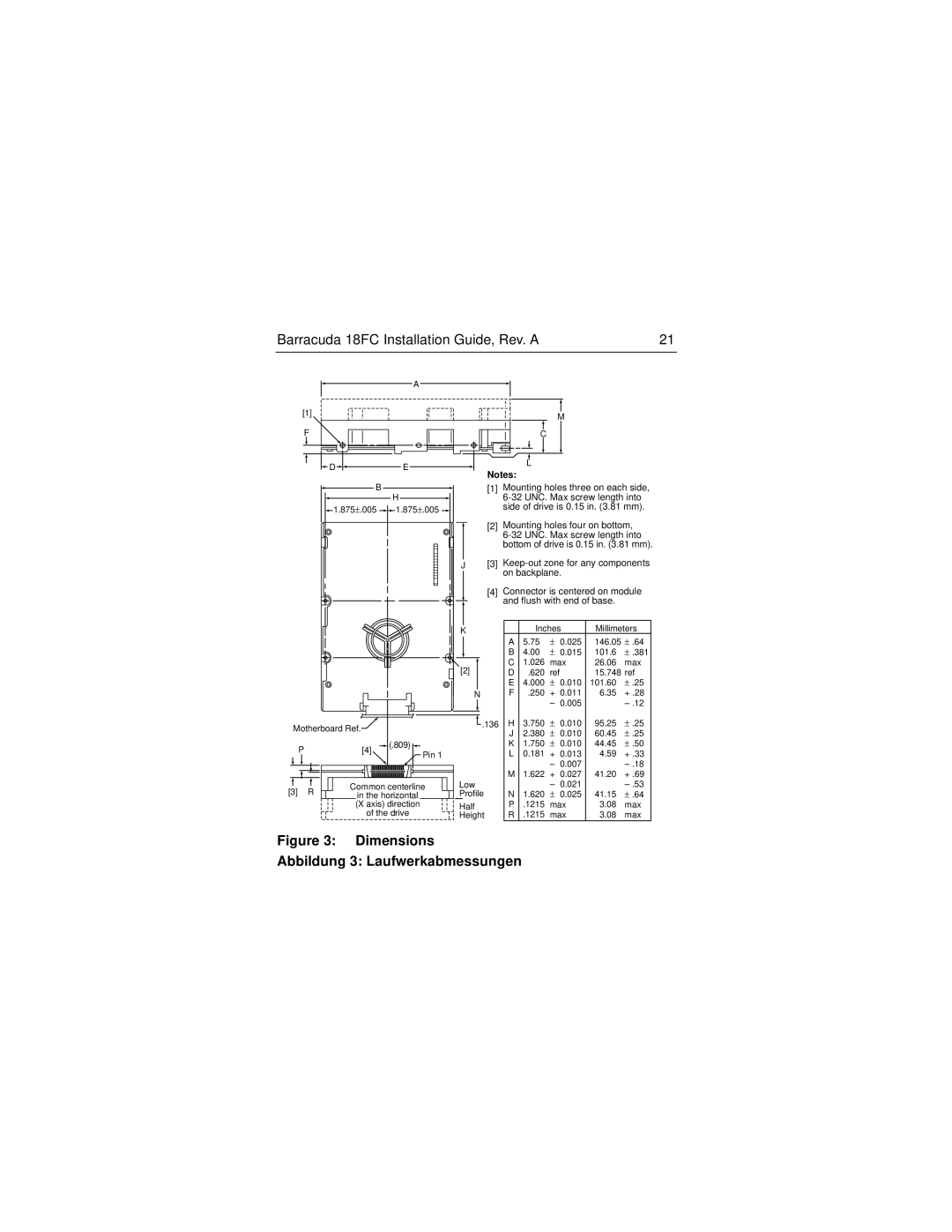
[1]Mounting holes three on each side,
[2] Mounting holes four on bottom,
J[3]
[4] Connector is centered on module and flush with end of base.
|
|
|
| K |
|
|
|
| [2] |
|
|
|
| N |
Motherboard Ref. |
|
| .136 | |
|
|
| ||
P | [4] | (.809) |
|
|
| Pin 1 |
| ||
|
|
|
| |
[3] R | Common centerline | Low | ||
in the horizontal |
| Profile | ||
| (X axis) direction |
| Half | |
| of the drive |
| Height | |
| Inches | Millimeters | |||
A | 5.75 | ± | 0.025 | 146.05 | ± .64 |
B | 4.00 | ± | 0.015 | 101.6 | ± .381 |
C | 1.026 | max | 26.060 max | ||
D | .620 | ref |
| 15.748 | ref |
E | 4.000 | ± | 0.010 | 101.600 | ± .25 |
F | .250 | + | 0.011 | 6.350 | + .28 |
|
| – | 0.005 |
| |
H | 3.750 | ± | 0.010 | 95.25 | ± .25 |
J | 2.380 | ± | 0.010 | 60.45 | ± .25 |
K | 1.750 | ± | 0.010 | 44.450 | ± .50 |
L | 0.181 | + | 0.013 | 4.590 | + .33 |
|
| – | 0.007 |
| |
M | 1.622 | + | 0.027 | 41.20 | + .69 |
|
| – | 0.021 |
| |
N | 1.620 | ± | 0.025 | 41.150 | ± .64 |
P | .1215 | max | 3.080 max | ||
R | .1215 | max | 3.080 max | ||