Cheetah 15K.4 Installation Guide
ST3146854LW/LC, ST373454LW/LC and ST336754LW/LC SCSI interface disc drives
Publication Number: 100220463, Rev. B, February 2004
Handling precautions/Electrostatic discharge protection
• Disc drives are fragile. Do not drop or jar the drive. Handle the drive only |
by the edges or frame. |
• Drive electronics are extremely sensitive to static electricity. Keep the |
drive in its antistatic container until you are ready to install it. Wear a wrist |
strap and cable connected to ground. Discharge static from all items near |
or that will contact the drive. Never use an ohmmeter on any circuit |
boards. |
• Turn off the power to the host system during installation. |
• Always use |
• Use caution when troubleshooting a unit that has voltages present. |
• Do not disassemble the drive; doing so voids the warranty. |
Installation instructions
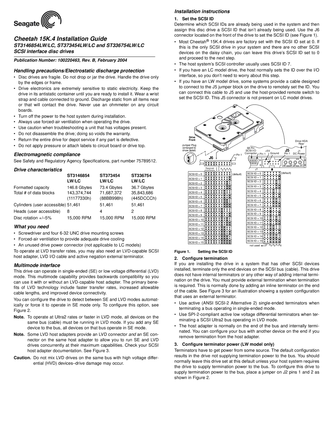
1. Set the SCSI ID
Determine which SCSI IDs are already being used in the system and then assign this disc drive a SCSI ID that isn’t already being used. Use the J6 connector located on the front of the drive to set the SCSI ID (see Figure 1).
•Most Cheetah® 15K.4 drives are factory set with the SCSI ID set at 0. If this is the only SCSI drive in your system and there are no other SCSI devices on the daisy chain, you can leave this drive’s SCSI ID set to 0 and proceed to the next step.
•The host system’s SCSI controller usually uses SCSI ID 7.
•If you have an LC model drive, the host normally sets the ID over the I/O interface, so you don’t need to worry about this step.
•If you have an LW model drive, some systems provide a cable designed to connect to the J5 jumper block on the drive to remotely set the ID. You can connect this cable to J5 and use the
• | Return the entire drive for depot service if any part is defective. |
• | Do not apply pressure or attach labels to circuit board or drive top. |
Electromagnetic compliance
See Safety and Regulatory Agency Specifications, part number 75789512.
Drive characteristics
| ST3146854 | ST373454 | ST336754 |
| LW/LC | LW/LC | LW/LC |
Formatted capacity | 146.8 Gbytes | 73.4 Gbytes | 36.7 Gbytes |
Total # of data blocks | 143,374,744 | 71,687,372 | 35,843,686 |
| (11177330h) | (88BB998h) | (445DCCCh) |
Cylinders (user accessible) 51,461 | 51,461 | 51,461 | |
Heads (user accessible) | 8 | 4 | 2 |
Disc rotation | 15,000 RPM | 15,000 RPM | 15,000 RPM |
What you need
• | Screwdriver and four |
• |
|
Drive
Front
Jumper Plug (enlarged to show detail)
J6 |
|
|
|
|
| Pin 1 |
|
|
|
|
|
| |
Reserved | L | R |
| A |
| A A |
E | E A | 3 | 2 | |||
| D | S |
| 1 0 | ||
SCSI ID = 0 |
|
|
|
|
| (default) |
SCSI ID = 1
SCSI ID = 2
SCSI ID = 3
SCSI ID = 4
SCSI ID = 5
SCSI ID = 6
SCSI ID = 7
SCSI ID = 8
SCSI ID = 9
SCSI ID = 10
SCSI ID = 11
SCSI ID = 12
SCSI ID = 13
SCSI ID = 14
SCSI ID = 15
68 Pin |
|
|
SCSI I/O | +5V | Ground |
Connector | Pin 1 |
J1
SCSI ID = 0
SCSI ID = 1
SCSI ID = 2
SCSI ID = 3
SCSI ID = 4
SCSI ID = 5
SCSI ID = 6
SCSI ID = 7
SCSI ID = 8
SCSI ID = 9
SCSI ID = 10
SCSI ID = 11
SCSI ID = 12
SCSI ID = 13
SCSI ID = 14
SCSI ID = 15
Drive HDA
Rear
J5 |
| J1 |
Pin 1 DC Power | ||
4P | 3P 2P | 1P |
(default)
• An unused drive power connector (not applicable to LC models) |
To operate at LVD transfer rates, you may also need an
Figure 1. Setting the SCSI ID
not used ![]() A3 A2 A1A0
A3 A2 A1A0
Multimode interface
This drive can operate in
You can configure the drive to detect between SE and LVD modes automat- ically or force it to operate in SE mode only. To configure this option, see Figure 2.
Note. To operate at Ultra2 rates or faster in LVD mode, all devices on the same bus (cable) must be running in LVD mode. If you add any SE device to the bus, all devices on that bus operate in SE mode.
Note. Some LVD host adapters provide an LVD connector and an SE con- nector on the same host adapter to allow you to run SE and LVD drives concurrently at their maximum capabilities. Check your SCSI host adapter documentation. See Figure 3.
Caution. Do not mix LVD drives on the same bus with high voltage differ- ential (HVD)
2. Configure termination
If you are installing the drive in a system that has other SCSI devices installed, terminate only the end devices on the SCSI bus (cable). This drive does not have internal terminators or any other way of adding internal termi- nation on the drive. You must provide external termination when termination is required. This is normally done by adding an inline terminator on the end of the cable. See Figure 3 for an illustration showing a system configuration that uses an external terminator.
•Use active (ANSI
•Use
•The host adapter is normally on the end of the bus and internally termi- nated. You can configure your bus with another device on the end if you remove termination from the host adapter.
3. Configure terminator power (LW model only)
Terminators have to get power from some source. The default configuration results in the drive not supplying termination power to the bus. You should normally leave this drive set at this default unless your host system requires the drive to supply termination power to the bus. To configure this drive to supply termination power to the bus, place a jumper on J2 pins 1 and 2 as shown in Figure 2.