• Remove the six hex nuts and lock washers which | • | To remove the front auger drive belt, push the idler | |||||||||||||||
attach the auger housing assembly to the frame |
| pulley to the left. See Figure 32 . The belt brake | |||||||||||||||
assembly. See Figure 30. |
| should move outward. Lift the front auger drive | |||||||||||||||
WARNING: Do not attempt to change the |
| belt from the front auger pulley. | |||||||||||||||
|
|
|
|
|
|
|
|
|
|
|
|
|
|
|
|
| |
auger belt without the help of an assistant. It is |
|
|
|
|
|
|
|
|
|
|
|
|
|
|
|
|
|
very important that one person, standing at the |
|
|
|
|
|
|
|
|
|
|
|
|
|
|
|
|
|
|
|
|
|
|
|
|
|
|
|
|
|
|
|
|
|
| |
operating position, firmly hold the snow thrower |
|
|
|
|
|
|
|
|
|
|
|
|
|
|
|
|
|
|
|
|
|
|
|
|
|
|
|
|
|
|
|
|
|
| |
|
|
|
|
|
|
|
|
|
|
|
|
|
|
|
|
| |
housing to prevent it from tipping while the |
|
|
|
|
|
|
|
|
|
|
|
|
|
|
|
|
|
|
|
|
|
|
|
|
|
|
|
|
|
|
|
|
|
| |
other person replaces the belt. Failure to |
|
|
|
|
|
|
|
|
|
|
|
|
|
|
|
|
|
|
|
|
|
|
|
|
|
|
|
|
|
|
|
|
|
| |
|
|
|
|
|
|
|
|
|
|
|
|
|
|
|
|
| |
comply may cause injury. |
|
|
|
|
|
|
|
|
|
|
|
|
|
|
|
|
|
|
|
|
|
|
|
|
|
|
|
|
|
|
|
|
|
| |
|
|
|
|
|
|
|
|
|
|
|
|
|
|
|
|
| |
|
|
|
|
|
|
|
|
|
|
|
|
|
|
|
|
|
|
|
|
|
|
|
|
|
|
|
|
|
|
|
|
|
|
|
|
|
|
|
|
|
|
|
|
|
|
|
|
|
|
|
|
|
|
|
|
|
|
|
|
|
|
|
|
|
|
|
|
|
|
|
|
|
|
|
|
|
|
|
|
|
|
|
|
|
|
|
|
|
|
|
|
|
|
|
|
|
|
|
|
|
|
|
|
|
|
|
|
|
|
|
|
|
|
|
|
|
|
|
|
|
|
|
|
|
|
Hex Nuts, ![]()
Lock
Washer | • |
|
Align |
studs for |
|
reassembly | • |
Auger
Idler Pulley
Figure 32
Place new belts on the two auger pulleys making sure that the front auger belt is under the belt brake. Route belts under and to the left of the flat idler pulley. Hold the belts upward in this position. While lifting up on the handles, bring the frame assembly close to the auger housing, and place the two belts on the front and rear engine pulleys. See Figure 33.
Figure 30
•Standing in the operating position, lift up on the handles and pull the frame assembly towards the rear. The frame and the housing will separate, and the rear auger belt will come off the pulley. Maintain control of the frame assembly while pulling it.
•Remove the two belts from the two engine pulleys. For location of the pulleys, see Figure 31 .
Auger Belt
Drive Belt
Rear
Engine
Pulley
Idler Pulley
Front
Engine
Pulley
Figure 31
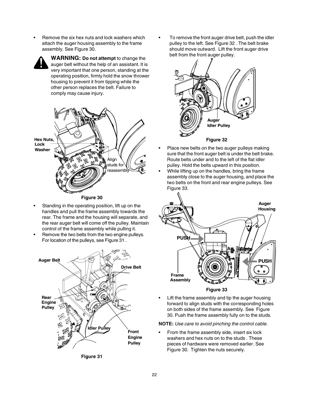
Auger
Housing
PUSH |
PUSH |
Frame
Assembly
Figure 33
•Lift the frame assembly and tip the auger housing forward to align studs with the corresponding holes on both sides of the frame assembly. See Figure 30. Push the frame assembly fully on to the studs.
NOTE: Use care to avoid pinching the control cable.
•From the frame assembly side, insert six lock washers and hex nuts on to the studs . These pieces of hardware were removed earlier. See Figure 30. Tighten the nuts securely.
22