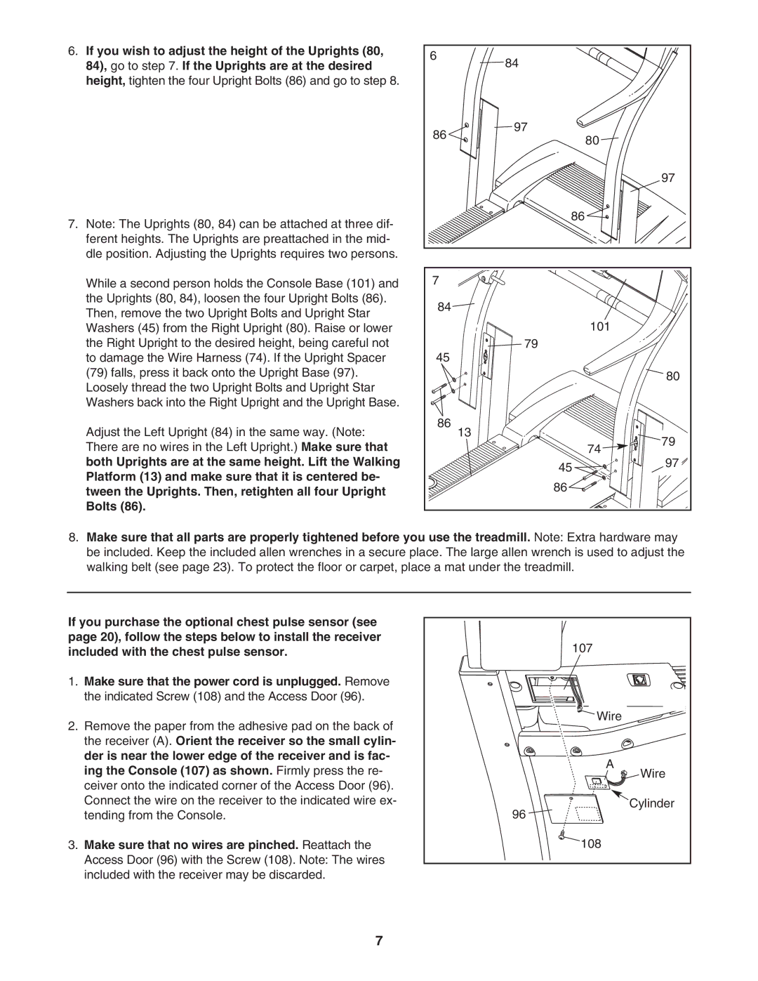
6.If you wish to adjust the height of the Uprights (80, 84), go to step 7. If the Uprights are at the desired height, tighten the four Upright Bolts (86) and go to step 8.
7.Note: The Uprights (80, 84) can be attached at three dif- ferent heights. The Uprights are preattached in the mid- dle position. Adjusting the Uprights requires two persons.
While a second person holds the Console Base (101) and the Uprights (80, 84), loosen the four Upright Bolts (86). Then, remove the two Upright Bolts and Upright Star Washers (45) from the Right Upright (80). Raise or lower the Right Upright to the desired height, being careful not to damage the Wire Harness (74). If the Upright Spacer
(79)falls, press it back onto the Upright Base (97). Loosely thread the two Upright Bolts and Upright Star Washers back into the Right Upright and the Upright Base.
Adjust the Left Upright (84) in the same way. (Note: There are no wires in the Left Upright.) Make sure that both Uprights are at the same height. Lift the Walking Platform (13) and make sure that it is centered be- tween the Uprights. Then, retighten all four Upright Bolts (86).
6 | 84 |
|
|
|
|
| |
86 | 97 | 80 |
|
|
| ||
|
|
| |
|
|
| 97 |
| 86 |
|
|
7 |
|
|
|
84 |
|
|
|
|
| 101 |
|
45 | 79 |
|
|
|
|
| |
|
|
| 80 |
86 | 13 |
|
|
|
| 79 | |
|
| 74 | |
|
| 97 | |
| 45 |
| |
|
|
| |
| 86 |
|
|
8.Make sure that all parts are properly tightened before you use the treadmill. Note: Extra hardware may be included. Keep the included allen wrenches in a secure place. The large allen wrench is used to adjust the walking belt (see page 23). To protect the floor or carpet, place a mat under the treadmill.
If you purchase the optional chest pulse sensor (see page 20), follow the steps below to install the receiver included with the chest pulse sensor.
1.Make sure that the power cord is unplugged. Remove the indicated Screw (108) and the Access Door (96).
2.Remove the paper from the adhesive pad on the back of the receiver (A). Orient the receiver so the small cylin- der is near the lower edge of the receiver and is fac- ing the Console (107) as shown. Firmly press the re- ceiver onto the indicated corner of the Access Door (96). Connect the wire on the receiver to the indicated wire ex- tending from the Console.
3.Make sure that no wires are pinched. Reattach the Access Door (96) with the Screw (108). Note: The wires included with the receiver may be discarded.
107 |
Wire |
A |
Wire |
Cylinder |
96 |
108 |
7