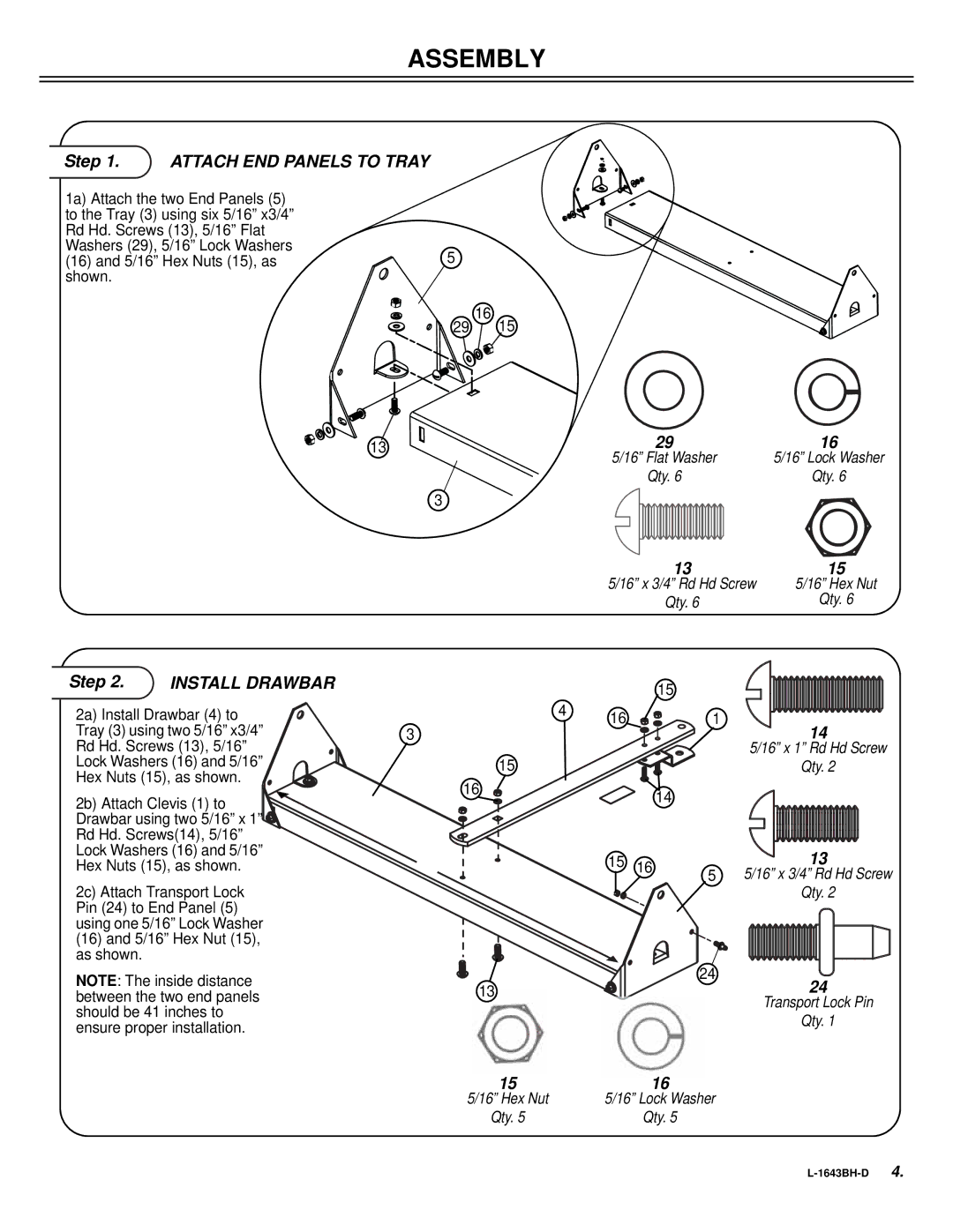
S A T - 4 0 B H specifications
The Sears S A T - 4 0 B H is a remarkable advancement in the landscape of agricultural machinery, designed to enhance the efficiency of farming operations. This versatile machine is tailored specifically for semi-automated cultivation, combining technology and reliability to meet the diverse needs of modern agriculture.One of the standout features of the S A T - 4 0 B H is its robust engine, powering the machine with impressive horsepower. This allows it to tackle heavy-duty tasks such as tilling, plowing, and planting with ease. The powerful engine is complemented by an advanced hydraulic system, which offers superior control over various attachments, ensuring that farmers can seamlessly switch between functions.
The S A T - 4 0 B H is engineered with precision agriculture in mind. It is equipped with GPS technology, allowing farmers to monitor their fields in real-time and optimize their planting patterns. This feature minimizes waste and maximizes yield by ensuring that seeds are sown at the optimal intervals. The onboard software provides detailed analytics, helping farmers to make informed decisions about crop management and resource allocation.
Another prominent feature is the machine's user-friendly interface. The dashboard is intuitively designed, providing easy access to essential controls and information. This not only enhances the user experience but also ensures that operators can focus on their farming tasks without being distracted by complicated controls.
The S A T - 4 0 B H is built with durable materials, ensuring longevity and reliability in various working conditions. Its heavy-duty construction can withstand the rigors of agricultural use, making it a worthwhile investment for any farmer.
Furthermore, the machine boasts a compact design, which allows it to maneuver easily in tight spaces, making it ideal for smaller farms or intricate field layouts. This versatility is further enhanced by the range of compatible implements, including seeders, cultivators, and harrows, enabling the S A T - 4 0 B H to perform multiple tasks throughout the farming season.
In conclusion, the Sears S A T - 4 0 B H is a state-of-the-art solution for farmers seeking to enhance productivity and efficiency. Its powerful engine, advanced technology, user-friendly design, and robust construction make it a standout choice for modern agricultural needs. This machine not only simplifies farming processes but also equips farmers with the tools they need to thrive in a competitive market.

