ENFORCER CCD IR Day/Night Camera Manual
ENFORCER CCD IR Day/Night Camera Manual
Specifications |
|
Type | Color camera |
Chip | 1/3” CCD, Sony |
Resolution | 420 TV lines |
Pickup elements | 510 x 492 pixels (NTSC / EIA) |
Scanning system | 2:1 interlace |
Sync | Internal |
Video output | |
Lens | 4.3mm, F2.0 fixed |
Minimum illumination | 0.4 lux (LED off), 0.0 lux (LED on) |
Gamma correction | 0.45 |
S/N ratio | >50dB (AGC off) |
Shutter control | Auto Electronic Shutter (AES) 1/60~1/100,000 sec. (NTSC) |
Backlight compensation | On |
Automatic gain control (AGC) | Auto |
Enclosure | IP66 weatherproof |
# of infrared LEDs | 18 |
Max. LED range | Up to 60 ft. (18m) |
Power source | 12VDC±10% |
Power consumption | 100mA (IR off), 280mA (IR on) |
Operating temperature | 14°~122° F |
Dimensions | 61/4”(L) x 215/16”(D) (158 x 74 mm) |
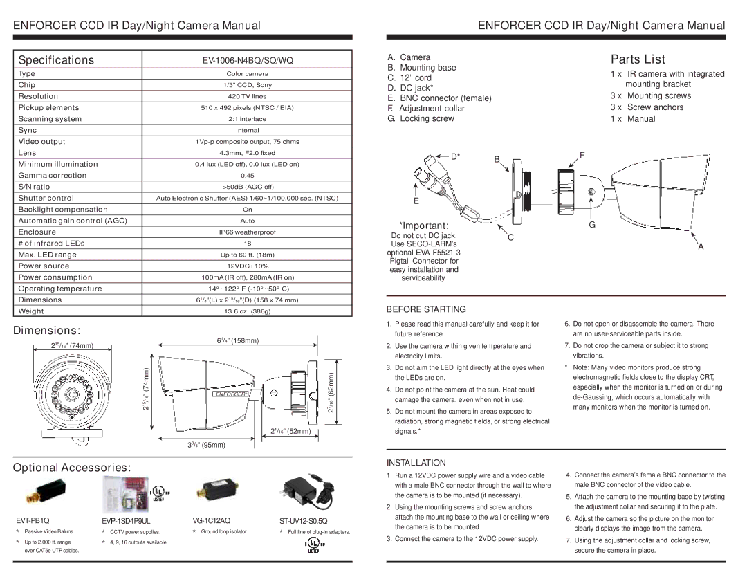
A.Camera
B.Mounting base
C.12” cord
D.DC jack*
E.BNC connector (female)
F.Adjustment collar
G.Locking screw
|
|
| D* | B |
|
|
| ||
|
|
|
| |
|
|
|
|
|
E |
| |||
*Important: |
| |||
Do not cut DC jack. | C | |||
Use |
| |||
optional |
| |||
Pigtail Connector for |
| |||
easy installation and |
| |||
serviceability. |
| |||
Parts List
1 x IR camera with integrated mounting bracket
3 x Mounting screws
3 x Screw anchors
1 x Manual
F
G
A
Weight | 13.6 oz. (386g) |
BEFORE STARTING
Dimensions:
215/16” (74mm)
61/4” (158mm)
1. | Please read this manual carefully and keep it for |
| future reference. |
2. | Use the camera within given temperature and |
| electricity limits. |
6.Do not open or disassemble the camera. There are no
7.Do not drop the camera or subject it to strong vibrations.
215/16” (74mm)
ENFORCER ®
33/4” (95mm)
21/16” (52mm)
27/16” (62mm)
3. | Do not aim the LED light directly at the eyes when |
| the LEDs are on. |
4. | Do not point the camera at the sun. Heat could |
| damage the camera, even when not in use. |
5. | Do not mount the camera in areas exposed to |
| radiation, strong magnetic fields, or strong electrical |
| signals.* |
*Note: Many video monitors produce strong electromagnetic fields close to the display CRT, especially when the monitor is turned on or during
Optional Accessories:
|
|
|
|
Passive Video Baluns. | CCTV power supplies. | Ground loop isolator. | Full line of |
O | O | O | O |
Up to 2,000 ft. range | 4, 9, 16 outputs available. |
|
|
O | O |
|
|
over CAT5e UTP cables. |
|
|
|
|
|
|
|
INSTALLATION
1.Run a 12VDC power supply wire and a video cable with a male BNC connector through the wall to where the camera is to be mounted (if necessary).
2.Using the mounting screws and screw anchors, attach the mounting base to the wall or ceiling where the camera is to be mounted.
3.Connect the camera to the 12VDC power supply.
4.Connect the camera’s female BNC connector to the male BNC connector of the video cable.
5.Attach the camera to the mounting base by twisting the adjustment collar and securing it to the plate.
6.Adjust the camera so the picture on the monitor clearly displays the image from the camera.
7.Using the adjustment collar and locking screw, secure the camera in place.